2.0 Installation
Separators/ Block
5
Chimney Unit
1
The installation of these elements is described in section 0.1.
2.4
Electrical Connections
Connection by a qualified electrician is recommended.
These models are designed only for single phase electrical supplies, or for two live
phases and neutral of a 3-phase supply. The product must be connected only to the type
and voltage of supply for which it was ordered.
Check that the supply voltage is compatible with the voltage on the label, and that the
current capacity is sufficient for the current on the label, before connection to the
electrical supply. A table of the most common ratings is given in section 11.0 towards
the back of this manual.
Normally a supply cable is not fitted, and connection is to be made to terminal blocks
accessed by removal of the left-hand end side cover (see section 8.3). The electrical
supply cable must be properly connected and fitted with an appropriate strain relief at
the entry to the case.
The electrical supply cable should be wired to an isolator or fitted with a line plug. The
isolator must be within easy reach of the operator, or the line plug must be easily
removable and on a lead not exceeding 3 m length. The line plug must allow the
protective earth (ground) to be connected before the supply conductors and to be
disconnected after them. The supply point must be marked as the disconnecting device
for the furnace.
The electrical supply MUST incorporate an earth (ground).
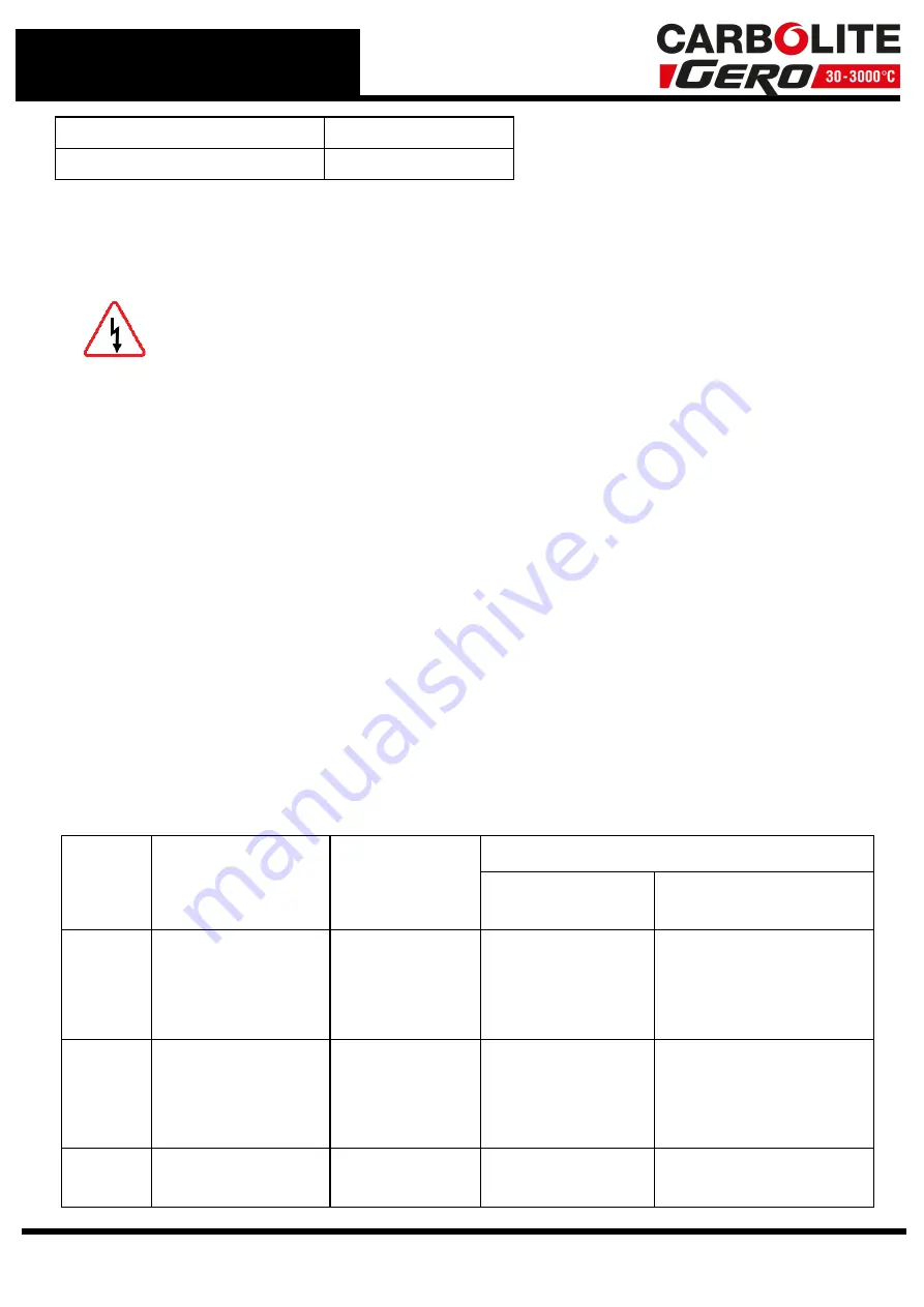
Supply
Terminal Label
Cable Colour
Supply Types
Live - Neutral
Reversible or Live-
Live
1-phase L
Brown
to live
to either power
conductor
(For USA 200-240V,
connect L1)
N
Blue
to neutral
to the other power
conductor
(For USA 200-240V,
connect L2)
PE
Green/ Yellow
to earth
(ground)
to earth (ground)
Electrical Connection Details:
10
Summary of Contents for CARBOLITE GERO HTF 18/8
Page 7: ...Caution Double Pole Neutral Fusing 7 1 0 Symbols and Warnings ...
Page 37: ...Power Limit View 37 4 0 3508 Dual Loop Cascade ...
Page 59: ...59 8 0 Repairs and Replacements ...
Page 64: ...10 0 Wiring Diagrams GR Y Green Yellow 64 ...
Page 68: ......
Page 69: ...Notes Service Record Engineer Name Date Record of Work ...


