background image

5.0   Maintenance

5.0

Maintenance

5.1

General Maintenance

Preventive rather than reactive maintenance is recommended. The type and frequency
depends on the product use; the following are recommended.

5.2

Maintenance Schedule

CUSTOMER

QUALIFIED PERSONNEL

DANGER! ELECTRIC SHOCK

. Risk of fatal injury. Only electrically

qualified personnel should attempt these maintenance procedures.

Maintenance

Procedure

Method

Frequency

Daily Weekly Monthly

Bi-

Annually

Annually

Safety

Over-Temperature Safety Circuit
(if fitted)

Set an over-temperature setpoint lower
than the displayed temperature and
check for an over-temperature alarm as
detailed in this manual

Over-Temperature Safety Circuit
(if fitted)

Electrical measurement

Safety Switch Function
(split models only)

Set a safe temperature above ambient,
and open the furnace to see if the heater
light goes out

Safety Switch Function
(split models only)

Electrical measurement

Electrical Safety (external)

Visual check of external cables and plugs

Electrical Safety (internal)

Physically check all connections and clean-
ing of the power plate area

Function

Temperature Calibration

Tested using certified equipment, fre-
quency dependent on the standard
required

Operational Check

Check that all functions are working nor-
mally

Operational Check

Thorough inspection and report incor-
porating a test of all functions

Work Tube Position

Visually check that the tube is central to
the heated zone (horizontally / vertically)

End Plugs / Radiation Shields

Visual check for damage or wear, and cor-

18

Summary of Contents for CARBOLITE GERO KZS 12/600

Page 1: ...Installation Operation and Maintenance Instructions 1200 C Large Tube Furnace KZS Model 600mm No Controller KZS 12 600 No Controller MEN KZS120600 16_NOCTRL 05 08 2019 ...

Page 2: ... 0 Temperature Controller 12 4 0 Operation 13 4 1 Operating Cycle 13 4 2 Control Method 13 4 3 3 Zone Control Methods 13 A Back to Back Thermocouples 14 B Retransmission of Setpoint 14 C Independent Control 15 4 4 General Operating Advice 15 4 5 Operator Safety 16 4 6 Tube Life 16 4 7 Pressure 16 4 8 Power Adjustment 17 4 9 Running at Low Temperatures 17 5 0 Maintenance 18 5 1 General Maintenance ...

Page 3: ...couple Replacement 23 6 6 Element Replacement 23 6 7 Fuse Replacement 24 7 0 Fault Analysis 25 A Furnace Does Not Heat Up 25 B Product Overheats 26 8 0 Wiring Diagrams 27 9 0 Fuses and Power Settings 28 9 1 Fuses 28 10 0 Specifications 29 10 1 Environment 29 Furnace drying out process 29 3 ...

Page 4: ...d to the elements Heat switch the switch disconnects power to the heating elements unless this switch is OFF there is a danger of electric shock when inserting objects into the product 1 2 General Warnings DANGER Electric shock Read any warning printed next to this symbol WARNING Risk of fatal injury DANGER Hot surface Read any warning printed next to this symbol WARNING All surfaces of a product ...

Page 5: ...Caution Double Pole Neutral Fusing 5 1 0 Symbols and Warnings ...

Page 6: ...of heat and on a non flammable surface that is resistant to accidental spillage or hot materials The surface on which the equipment is mounted should be stable and not subject to movement or vibrations The height of the mounting surface is important to avoid operator strain when loading and unloading samples Unless otherwise stated elsewhere in this manual ensure that there is at least 150 mm of f...

Page 7: ...on shields is similar to that of plugs If stainless steel seals with gas inlets are supplied they are to be fitted as shown in fig 3 the stem of any insulating plug should touch the seal For vertical models with stainless steel seals a hook and eye arrangement holds the upper insulating plug assembly Horizontal models if heavy fittings are to be clamped to the end of an extended work tube they can...

Page 8: ...2 0 Installation Fig 1 Insulating Plug standard length tube Key A Tube B Insulating Plug C Stem Fig 2 Insulating Plug long work tube 8 ...

Page 9: ...p End Seal For assembly details refer to the separate work tube end seal manual Under no circumstances should any objects be placed on top of the product Always ensure that any vents on the top of the product are clear of any obstruction Always ensure all cooling vents and cooling fans if fitted are clear of any obstruction 2 3 Electrical Connections Connection by a qualified electrician is recomm...

Page 10: ...ctory fitted supply cable are designed to be wired directly to an isolator or fitted with a line plug Products without a factory fitted supply cable require a permanent connection to a fused and isolated supply The product s electrical access panel should be temporarily removed and connections made to the internal terminals If the product is to be connected by line plug The plug should be within r...

Page 11: ...o phase 2 L3 Black to phase 3 N Light Blue to neutral except delta PE Green Yellow to earth ground DO NOT connect a product ordered for three phase use to a single phase supply or to the wrong type of three phase supply 11 2 0 Installation ...

Page 12: ...3 0 Temperature Controller 3 0 Temperature Controller If this product is fitted with a temperature controller instructions are provided separately 12 ...

Page 13: ...f the over temperature circuit has tripped an indicator on the over temperature controller flashes and the heating elements are isolated Find and correct the cause before resetting the over temperature controller according to the instructions supplied To switch off power to the heating elements use the heater switch To switch the product off use both the heater switch and the instrument switch If ...

Page 14: ...losses at the end or where using a gas flow However the sum of the centre zone controller setpoint and the end zone controller offset MUST NOT exceed the furnace maximum temperature To alter the setpoint with the display showing the Home screen press Down or Up once to display the setpoint and then press again or hold down to adjust it The display returns to the measured temperature when no key is...

Page 15: ...gative value This will then be added to or subtract from the end zone set temperature There is no need to alter the centre zone controller C Independent Control The three controllers are completely independent Note that it is not possible to maintain very different temperatures in the three zones because of heat transfer between the zones The models listed in this manual are designed to achieve an...

Page 16: ...iece and the tube crucibles or boats should be of low thermal mass and should have feet to reduce the contact with the tube fig 4 Key A Tube B Crucible Fig 4 Avoidance of thermal contact Do not set too high a heating or cooling rate As tubes are susceptible to thermal shock and may break Tubes which extend beyond the heated part of the furnace are more at risk A general rule for maximum heating or...

Page 17: ...tual supply voltage The models covered by this manual are designed for use over the range of voltages 200 V 250 V or if ordered 100 V 125 V and the power limit parameter is set accordingly These models may be adjusted to a different voltage within the range the power limit should be reset to match OP Hi see 9 0 Refer to section 3 0 for power adjustment instructions 4 9 Running at Low Temperatures ...

Page 18: ...ure Safety Circuit if fitted Electrical measurement Safety Switch Function split models only Set a safe temperature above ambient and open the furnace to see if the heater light goes out Safety Switch Function split models only Electrical measurement Electrical Safety external Visual check of external cables and plugs Electrical Safety internal Physically check all connections and clean ing of the...

Page 19: ...ck all seals and O rings and clamps Performance Element Circuit Electrical measurement Power Consumption Measure the current drawn on each phase circuit Cooling Fans if fitted Check whether the cooling fans are work ing 19 5 0 Maintenance ...

Page 20: ...fe temperature above ambient The heater lights should illuminate l Open the door and check the heater lights They should no longer be illuminated If the heater lights remain illuminated when the door is open discontinue use and contact Carbolite Gero Service Annual check The following checks should be carried out by a qualified electrician as specified in the Maintenance Schedule section of this m...

Page 21: ...d and the necessary parts to be despatched In all correspondence please quote the serial number and model type given on the rating label of the product The serial number and model type are also given on the back of this manual when supplied with the product Carbolite Gero Service and Carbolite Gero contact information can be found on the back page of this manual 5 5 Recommended Spare Parts and Spa...

Page 22: ... higher levels may be encountered during maintenance or repair Whilst there is no evidence of any long term health hazards it is strongly recommended that safety precautions are taken whenever the materials are handled Exposure to fibre dust may cause respiratory disease When handling the material always use approved respiratory protection equipment RPE eg FFP3 eye protection gloves and long sleev...

Page 23: ...onnections Thermocouple cable colour codings are thermocouple leg colour positive type N pink negative white Disconnect the thermocouple from its terminal block Carefully withdraw the thermocouple from the product and remove any broken bits of thermocouple Bend the new thermocouple carefully to match the shape of the original working from the terminal end Should the length differ from that of the ...

Page 24: ...ect all the wiring according to the plan previously made and complete the reassembly of the product Check that the product is controlling properly to rule out the possibility that the element failed because of a fault in the control system 6 7 Fuse Replacement Fuses are marked on the wiring diagram with type codes e g F1 F2 For more information on fuses refer to section 9 0 Depending on model and ...

Page 25: ...The door switch es if fitted may be faulty or need adjustment The contactor relay if fitted may be faulty The heater switch if fitted may be faulty or need adjustment The SSR could be failing to switch on due to internal failure faulty logic wiring from the controller or faulty controller There are no lights glowing on the controller Check the supply fuses and any fuses in the furnace control comp...

Page 26: ...aulty The controller shows a low temperature The thermocouple may be faulty or may have been removed out of the heating chamber The thermocouple may be connected the wrong way around The controller may be faulty 2 Product heats up when the instrument switch is OFF The SSR has failed ON Check for an accidental wiring fault that could have overloaded the SSR 26 ...

Page 27: ...8 0 Wiring Diagrams For wiring diagrams please contact Carbolite Gero Service Please quote the serial number and model 27 8 0 Wiring Diagrams ...

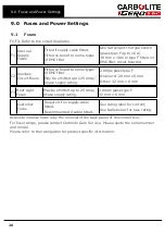
Page 28: ...y be omitted up to 25 Amp phase supply rating 2 Amps glass type F On board 20 mm x 5 mm Other 32 mm x 6 mm F3 Heat Light Fuses May be omitted up to 25 Amp phase supply rating 2 Amps glass type F 32 mm x 6 mm Customer Fuses Required if no supply cable fitted Recommended if cable fitted See rating label for current See table below for fuse rating Access to internal fuses is by the removal of the bac...

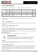
Page 29: ...e 30 C the allowed external temperature defined in EN 61010 1 2010 may be exceeded Relative humidity Maximum 80 up to 31 C decreasing linearly to 50 at 40 C Important safety notice After transportation or storage in humid conditions the furnace could fail to meet all the safety requirements of BSEN 61010 2 010 until it has completed the drying out process to restore its normal condition Warning It...

Page 30: ... manually on furnaces with basic control option or programmed into the controller if an advanced control option is fitted l Ramp the setpoint temperature 2 C minute to 100 C and dwell for 2 hours l Ramp the setpoint temperature 2 C minute to 300 C and dwell for 3 hours l Ramp the setpoint temperature 3 C minute to 1100 C and dwell for 1 hour l Cool naturally to ambient temperature l Furnace drying...

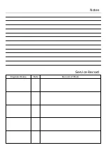
Page 31: ...Notes Service Record Engineer Name Date Record of Work ...

Page 32: ... us at the address below or ask your nearest stockist For preventive maintenance repair and calibration of all furnace and oven products please contact Carbolite Gero Service Telephone 44 0 1433 624242 Fax 44 0 1433 624243 Email ServiceUK carbolite gero com Carbolite Gero Ltd Parsons Lane Hope Hope Valley S33 6RB England Telephone 44 0 1433 620011 Fax 44 0 1433 621198 Email Info carbolite gero com...

Reviews: