background image

 17


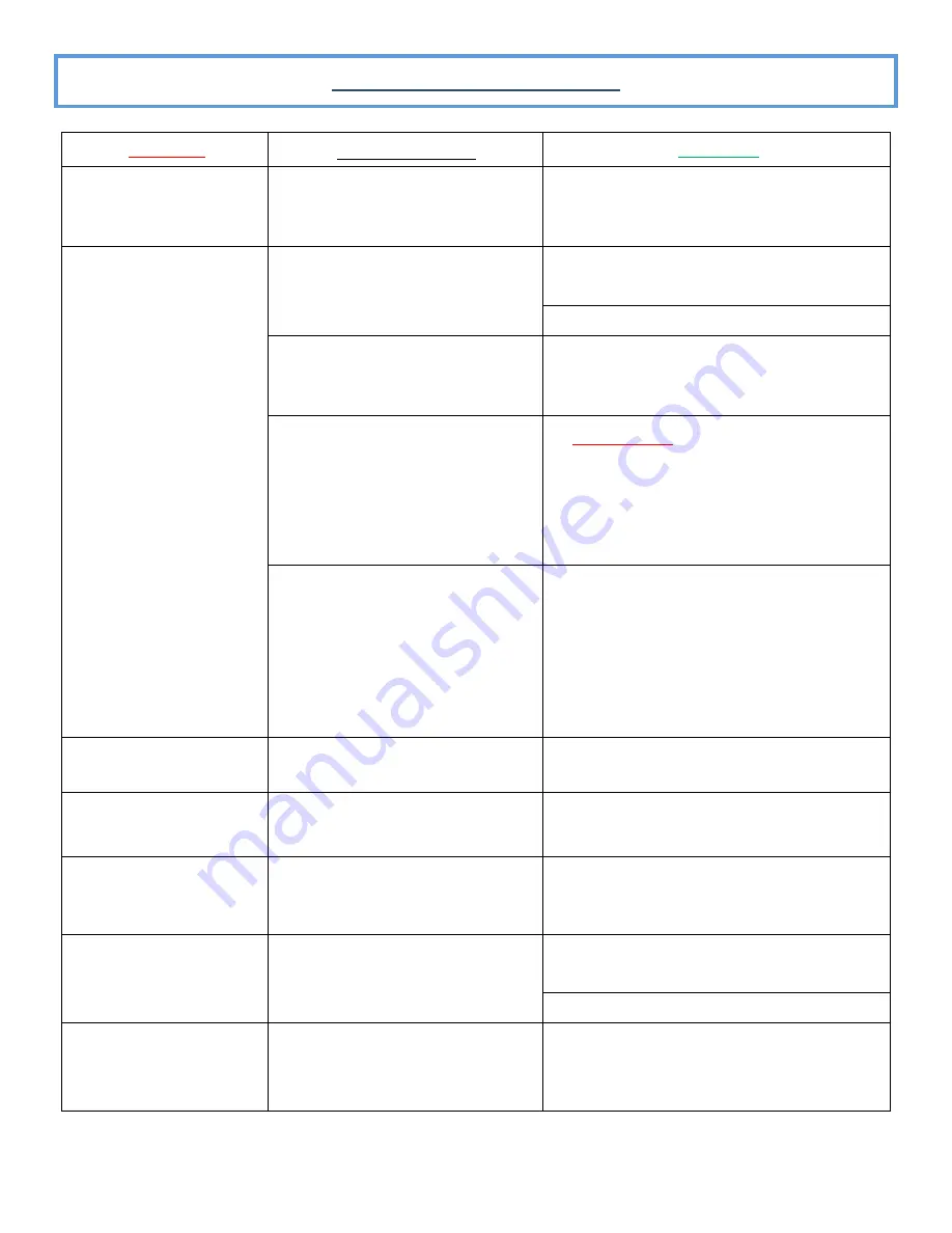
PROBLEM


POSSIBLE CAUSE


SOLUTION


NO OZONE


NO POWER TO SYSTEM PLUG


CHECK POWER SUPPLY CORD IS SEATED INTO 

VERIPURE SYSTEM AND WALL OUTLET.


RESET ANY GFI OUTLET RESET BUTTONS IN THE 

AREA.


CHECK IN

-

HOME ELECTRICAL BREAKER.


FILTER LIFE IS EXPRIRED AND FILTER


IS LIMITING WATER PRESSURE TO


FLOW

 SWITCH.


CHANGE YOUR SYSTEM FILTERS


WET GLASS DIELECTRIC


*CAREFULLY* 

REMOVE THE GLASS


DIELECTRIC AND INSPECT FOR


MOISTURE. IF WET, CONTACT VERIPURE 2425 

Hutson Road Green Bay, WI 54303


920.613.6771


DROP IN HOUSE OR MUNICIPLE WA-

TER PRESSURE.


LOW WATER PRESSURE WILL NOT


ALLOW YOUR SYSTEM OZONATION


COMPONENTS TO TURN ON. REGAIN


INCOMING WATER PRESSURE TO


MINIMUM OF 50 PSI. CONTACT YOUR PLUMBER 

OR MUNICIPALITY.


DROP IN OR NO WATER 

FLOW


PLUGGED FILTER


CHANGE YOUR SYSTEM FILTERS.


DROP IN HOUSE OR MUNICIPLE 


WATER PRESSURE.


CONTACT YOUR PLUMBER OR 


MUNICIPALITY.


SYSTEM LIGHTS NOT ON


NO POWER TO SYSTEM PLUG.


CHECK POWER SUPPLY CORD IS SEATED INTO 

VERIPURE SYSTEM AND WALL


OUTLET.


RESET ANY GFI OUTLET RESET BUTTONS IN THE 

AREA.


CHECK IN

-

HOME ELECTRICAL BREAKER.


PANEL INDICATION 
LIGHTS HAVE NOT        
RETURNED TO STANDBY


MAY HAVE NOT UNPLUGGED POWER


WHEN CHANGING FILTER/GLASS         
DIELECTRIC TUBE.


UNPLUG YOUR SYSTEM, WAIT 10  SECONDS 

PLUG BACK IN AND PRESS


THE  RESET BUTTON 

ON YOUR FRONT PANEL.


TROUBLE SHOOTING CHART


Summary of Contents for VERIPUREVPC5000

Page 1: ...1 REVISED 4 13 2020 OWNERS MANUAL VERIPUREVPC5000...

Page 2: ...m THANK YOU FOR CHOOSING VERIPURE PLEASE TAKE A FEW MOMENTS TO FILL IN THE INFORMATION BELOW SAVE THIS MANUAL AS A CONVENIENT INFORMATION SOURCE FOR YOUR VERIPURE SYSTEM Date of Purchase Purchased Fro...

Page 3: ...ystems certified for cyst reduction may be used on disinfected waters that may contain filterable cysts Stage One Filtration Process The VeriPure Maintenance Kit Consists of a two filter configuration...

Page 4: ...HE WATER SUPPLY AT THE SINK OR WATER SOURCE AND UNPLUG POWER JACK FROM THE VERIPURE SYSTEM BEFORE PERFORMING ANY MAINTENANCE ACCESSORIES DO NOT USE ANY ACCESSORIES INCLUDING FILTER CARTRIDGES THAT ARE...

Page 5: ...OR 3 MINUTES WITH VERIPURE WATER FOOD ITEMS PLACE IN A BOWL COLANDER OR STRAINER RINSE WITH VERIPURE WATER STORING WATER SELECT A CONTAINER THAT IS FOOD GRADE QUALITY SUCH AS GLASS OR STAINLESS STEEL...

Page 6: ...6 A LOOK AT YOUR VERIPURE SYSTEM UNIT DIMENSIONS 11 5 L X 7 W X 5 5 H 9 0LBS 4 05KG IT IS IMPORTANT TO BE FAMILIAR WITH CERTAIN COMPONENTS OF YOUR VERIPURE SYSTEM FOR MAINTENANCE PURPOSES DIAGRAM 1...

Page 7: ...FORMANCE LIMIT YOUR VERIPURE SYSTEM TO 70 PSI OF WATER PRESSURE VERIPURE RECOMMENDS A MINIMUM WATER PRESSURE OF 50 PSI LOW WATER PRESSURE WILL CAUSE YOUR VERIPURE SYSTEM TO PRODUCE A LOWER QUANTITY OF...

Page 8: ...of the VeriPure System must conform to state and local plumbing and electrical codes laws regulations and the instructions provided with your VeriPure System Failure to install as instructed will voi...

Page 9: ...Pure System Step 4 Mount screws for the VeriPure System by using the provided screws and mounting plate Step 5 Locate the 1 4 filter inlet fitting on your VeriPure System Remove the 3 8 red locking cl...

Page 10: ...valve in your preferred location and then hand tighten the diverter valve collar Step 6 Connect power cord to the VeriPure System and plug into wall outlet Step 7 To operate your VeriPure System turn...

Page 11: ...REQUIRED PLACE THESE PADS APPROXIMATLY 1 5 INCHES FROM THE END OF EACH CORNER FOR FILTER DOWN POSITION FOR DIELECTRIC UP POSITION THE TOP SIDE OF BOTTOM SIDE THAT REST AGAINST WALL WILL RECEIVE 2 PADS...

Page 12: ...is malfunctioning LED READOUT INSTALLED VERIPURE There are two maintenance requirements for your VeriPure System 1 Change the filter cartridge assembly when indicated by the LED readout on your VeriP...

Page 13: ...ose s you can damage unit fittings See Warranty Specifications TO REMOVE THE FILTER CARTRIDGES 1 Place a towel absorbent cloth on counter or work surface 2 Remove unit from wall mounting plate by loos...

Page 14: ...e locking bolt and turn finger tight RETURNING UNIT TO USE 1 If wall mounted line up mounting guide holes to guide bolts on mounting plate Allow unit to seat into place checking stability before relea...

Page 15: ...ck 4 Slowly remove the Dielectric tube from the VeriPure housing by sliding the Dielectric out IN A STRAIGHT LINE until the Dielectric tube is completely separated from the VeriPure housing 5 The old...

Page 16: ...E OF WATER LEAKAGE If a water leak is detected REPEAT Returning Unit to use Steps 2 4 TROUBLE SHOOTING GUIDE At VeriPure Inc we expect your VeriPure System to function properly for years as long as yo...

Page 17: ...SURE WILL NOT ALLOW YOUR SYSTEM OZONATION COMPONENTS TO TURN ON REGAIN INCOMING WATER PRESSURE TO MINIMUM OF 50 PSI CONTACT YOUR PLUMBER OR MUNICIPALITY DROP IN OR NO WATER FLOW PLUGGED FILTER CHANGE...

Page 18: ...OES THE OZONE AFFECT THE TASTE OF THE WATER Initially there is a slight aroma of ozone This dissipates after a short period of time approximately 20 seconds IS THE OZONE GAS RELEASED INTO THE AIR BY V...

Page 19: ...veripure com in a timely manner following discovery of the claimed defect Any claim under this warranty must be made within 30 days following the expiration of the one year warranty Badger VeriPure LL...

Reviews: