3
reversing the connection. For more info on connecting LEDs to your motherboard,
see your motherboard manual.
5.
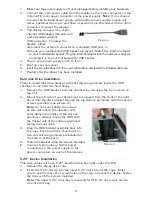
The Hard Drive LED (labeled HDD LED) connects to the hard drive activity header.
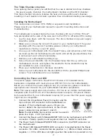
Power Supply 3-Pin Fan Signal Connector
A three-pin fan signal connector with blue and black wires is available to connect
the power supply to one of your motherboard’s fan connectors (
Note
: Some
motherboards have a dedicated fan connector labeled PWR_FAN or PSU_FAN that
is specifically for the power supply). This connector is for monitoring the power
supply’s fan speed only. It is optional. The power supply and its fan will operate
normally whether this cable is connected to your motherboard or not.
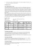
The fan speed can be monitored through the BIOS or special monitoring software
that came with your motherboard. To ensure proper monitoring of the power supply
fan, please check your motherboard manual.
Note:
At low temperatures, the fan may run as slow as 750 RPM (±10%). At
these speeds, some motherboards may not properly detect the fan speed and may
generate false warnings of fan failure.
Connecting the USB Ports
You will find a single 10-pin connector on a cable attached to the front USB ports.
This is an Intel® standard connector that is keyed so that it can’t be accidentally
reversed when connected to a proper Intel® standard motherboard header. Connect
the 10-pin connector to the motherboard headers so that the blocked pin fits over
the missing header pin.
Note:
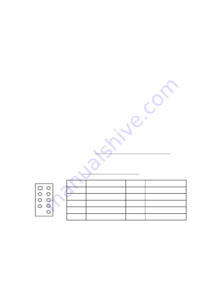
Please check the motherboard manual for the USB header pin layout and
make sure it matches the table below. If it does not match this Intel® standard,
please visit Antec’s web store at http://www.antec.com/StoreFront.bok and
search for part number 30095 to order a USB Internal Adapter Cable. This adapter
will allow you to connect the front USB to your motherboard on a pin-by-pin basis.
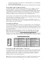
Motherboard USB Pin Layout
Connecting the IEEE 1394 (FireWire®, i.Link®) Port
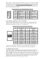
You will find a single 10-pin connector on a cable attached to the front IEEE 1394
connection. This is an Intel® standard connector that is keyed so that it can’t be
accidentally reversed when connected to a proper Intel® standard motherboard
header. Connect the 10-pin connector to the motherboard header so that the
blocked pin fits over the missing header pin.
Note:
Please check the motherboard manual for your IEEE 1394 header pin layout
and make sure it matches the table below. If you intend to connect the front
Pin
Signal Names
Pin
Signal Names
1
USB Power 1
2
USB Power 2
3
Negative Signal 1
4
Negative Signal 2
5
Positive Signal 1
6
Positive Signal 2
7
Ground 1
8
Ground 2
9
Key (No Connection)
10
Empty Pin
1
2
10
9


