5
1. Make sure the power supply is off and unplugged before installing any hardware.
2.
Connect the 3-pin power cable from the display to the 3-pin connector on the
24-pin ATX main power connector of the power supply.
Note
: If you choose
to swap the included power supply with another power supply, please call
Antec Customer Service to purchase a special 24-pin Extender with the 3-pin
connector to power the display.
3.
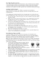
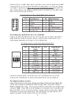
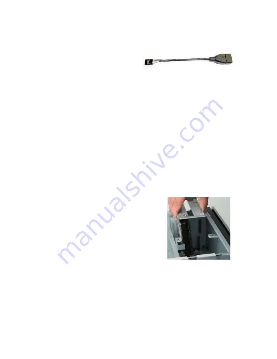
The display comes with a 4-pin
internal USB adapter (see picture 3)
and a standard external
USB connector. To power the
display, either:
a)Connect the external connector to a standard USB port, or
b) Check your motherboard USB header pin layout. Match the internal adapter
to your motherboard header. Plug the internal adapter into the external connector
and plug it in to your motherboard’s USB header.
4. Plug in your power supply and turn it on.
5. Boot up your computer.
6. Insert the provided driver CD into your optical drive and install the included software.
7. Restart after the driver has been installed.
Hard disk Drive Installation
There is a hard disk drive bracket with soft silicone grommets inside the HDD
chamber. It can hold two hard drives.
1.
Remove the HDD bracket from the chamber by removing the two screws on
top of it.
2.
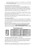
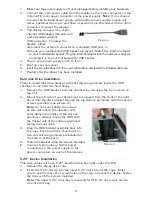
Mount the left side of your hard drives (as viewed from the front of the hard
drive) onto the drive bracket through the top silicone grommets with the special
screws provided (see picture 4).
Note:
Do not over-tighten the screws
as this will reduce the vibration and
noise-dampening ability of the silicone
grommets. Always mount the HDD with
the thicker side of the silicone grommets
facing the hard drive.
3.
Drop the HDD/bracket assembly back into
the case. Each hard drive should rest on
two soft silicone grommets preinstalled at
the bottom of the case.
4. Fasten the bracket using the screws provided.
5.
Connect 4-pin molex or SATA power
connectors on the power supply to the
power connectors on each of the devices.
5.25” Device Installation
This case comes with one 5.25” external drive bay right under the VFD.
1. Remove the flip-up drive cage.
2.
Insert the 5.25” device into the lower 5.25” drive bay of the cage. Make
sure to use the rear set of screw holes on the cage to mount the device. Fasten
the drive with the screws included.
Note:
The upper 5.25” drive bay is reserved for VFD. Do not mount any de-
vice into this bay.
Picture 3
Picture 4

