

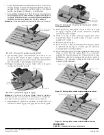

Joinery Table
Introduction
The Veritas Joinery Table is designed to be used with the Festool Domino Joiner DF 500 to create accurately placed and aligned
mortises for loose-tenon joinery. It increases the stability of the Domino, especially when working on narrower workpieces.
Caution:
To use this product safely,
always
follow the safety instructions that came with the Festool Domino Joiner.
As with any power tool accessory,
always
wear proper eye protection and hearing protection.
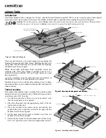
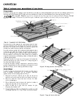
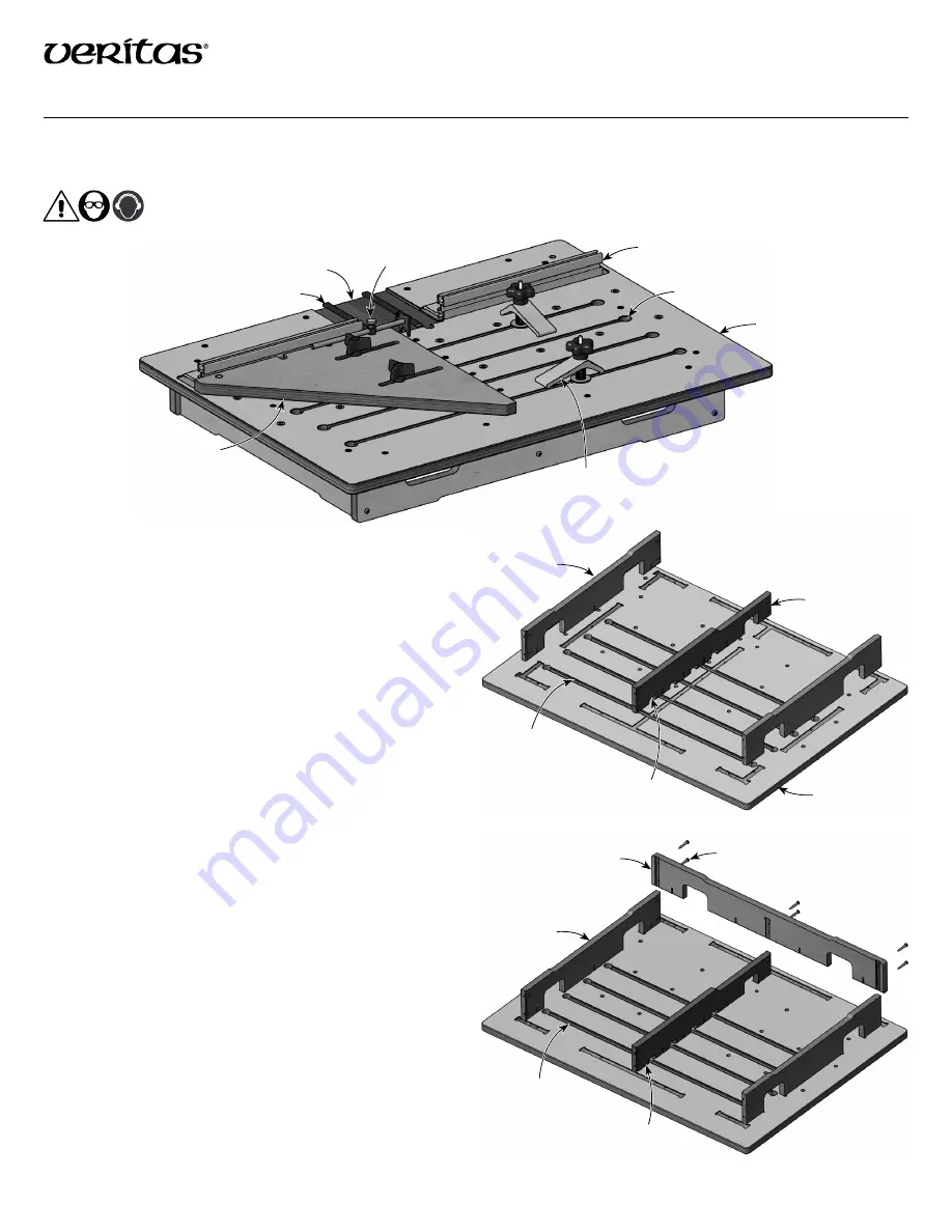
The base unit features a recessed opening for mounting the
Domino between the split fixed fences. Multiple keyhole slots
run parallel with the fixed fence to provide tracks for mounting
the hold-downs from any point.
While the movable right-angle fence accurately locates the
workpiece, the offset gauge makes it possible to move it to a
mirrored location so that the “left” and “right” halves of a joint
line up perfectly.
A pair of 6 mm shims is used to adjust the 5 mm vertical offset of
the mortise to 10 mm or 11 mm from the base surface.
The frame has cut-outs on all four sides, making it easy to clamp
the joinery table to your workbench when needed, and remove it
when not in use.
Table Assembly
The joinery table requires some assembly. The parts have been
designed for ease of assembly using a Robertson (square-drive)
screwdriver and a 5/32
"
hex key.
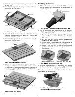
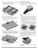
1. Lay the base panel face down on your work surface, such
that the frame grooves face upward.
2. Place the side panels into the appropriate grooves. The two
side panels are identical.
3. Place the stretcher in the center groove between the side
panels, being sure to align the cut-outs in the edge with the
keyhole slots in the base panel.
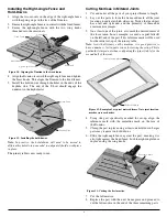
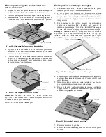
4. Set the back panel in the grooves furthest away from the
keyhole slots in the base panel.
5. Secure the back panel to the side panels and stretcher using
#8 × 1 1/4
"
pan-head screws. Do not overtighten these screws.
Figure 1: Joinery Table parts.
Right-Angle Fence
Recessed Opening for
Domino (not included)
Offset Gauge
Keyhole Slot
Fixed Fence
Hold-Down
Shim
Base
Figure 2: Locating the side panels and stretcher.
Figure 2: Locating the side panels and stretcher.
Base Panel
Side Panel
Keyhole Slot
Cut-Out
Stretcher
Figure 3: Attaching the back panel.
#8 × 1 1/4
"
Pan-Head Screw
Back Panel
Side Panel
Stretcher
Keyhole Slot


