
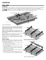

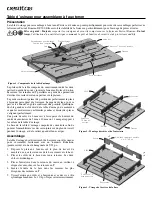
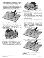

6. Set the front panel in the remaining grooves closest to the
keyhole slots.
7. Attach the front panel to the side panels and stretcher with
#8 × 1 1/4
"
pan-head screws.
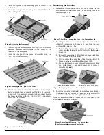
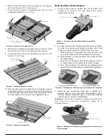
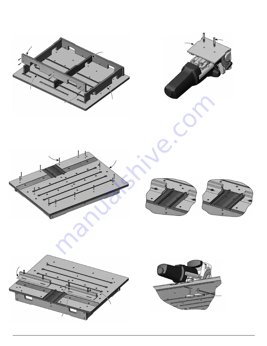
8. Carefully flip the entire assembly over, right side up. Ensure
the frame members are still located in the grooves in the
underside of the base panel.
9. Secure the base panel to the frame and stretcher using the
#8 × 1 3/4
"
flat-head screws.
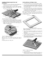
10. Place the two aluminum fixed fences in the milled cavity in
the top and push them against the milled sides of the cavity
to ensure the two fences are aligned with each other. Secure
the fences in place with the 1/4-20 × 3/4
"
button-head
screws and 1/4
"
washers.
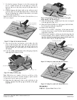
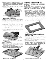
Mounting the Domino
1. Thread the two mounting studs into the M5 holes in the
bottom of the Domino base plate. The mounting studs need
only be finger tight.
2. Use the pair of 6 mm thick shims to adjust the 5 mm vertical
offset of the mortise to 10 mm or 11 mm from the base
surface of the joinery table.
a. To establish a 10 mm vertical offset, place the 6 mm thick
shims into the slots in the milled cavity for the Domino
base plate.
b. For an 11 mm vertical offset, butt a 6 mm thick shim
against either side of the cavity.
c. With no shims, the center line of the Domino bit will be
5 mm from the base surface of the joinery table.
d. If a greater range of offsets is desired, an accessory shim
pack with 2 mm, 4 mm and 8 mm pairs of shims is
available separately.
3. Insert the mounting studs in the Domino base plate through
the holes in the base surface of the joinery table. Secure with
two brass knobs. Do not fully tighten the knobs.
Note:
You may need to move the fixed fence to clear some of the
adjustment knobs on the Domino.
Base Panel
#8 × 1 3/4
"
Flat-Head Screw
Figure 5: Securing the base panel to the frame.
Figure 8: Adjusting the vertical offset with shims.
6 mm shims placed in the slots
6 mm shims placed on the sides
Figure 6: Attaching the fixed fences.
1/4-20 × 3/4
"
Button-Head Screw
Fixed Fence
1/4
"
Washer
Figure 7: Installing the mounting studs in the Domino base plate.
Mounting Stud
Domino Base Plate
Figure 9: Installing the Domino to the base surface.
(Panel frame members removed for clarity.)
Brass Knob
2
Stretcher
Front Panel
Side Panel
Keyhole Slot
#8 × 1 1/4
"
Pan-Head Screw
Figure 4: Attaching the front panel.


