Installing the Right-Angle Fence and
Hold-Downs
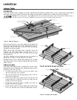
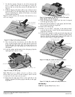
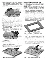
1. Align the two cut-outs in the edge of the right-angle fence
with the spring stops in the face of the Domino.
2. Ensure the right-angle fence is in contact with the fixed fences.
3. Secure the right-angle fence with the two wing knobs
threaded into the insert nuts.
4. Align the Domino face with the right-angle fence and tighten
the brass knobs. This aligns the Domino to the fixed fences.
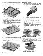
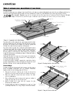
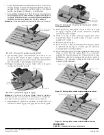
5. Install the hold-downs through the holes in the ends of the
keyhole slots. The end of the T-bolt should engage the
undercut in the keyhole slot.
Note:
In practice, the hold-downs will need to be moved to
different keyhole slots, as needed, to adequately hold a workpiece
in place.
The joinery table is now ready to use.
Cutting Mortises in Mitered Joints
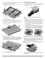
1. Cut and miter all the parts of your project/frame to length.
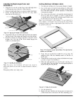
2. Lay out the parts to form the frame and mark all the joint
locations to indicate which side is up. Notice that each part
has a left and right end, and the geometry of these ends
creates mirror images.
3. On at least one of the joints, also mark the desired center of
the loose tenon. In our example, we used a capital letter R
on the left end of the part. This reference mark will be used
for the initial set-up of the joinery table.
Note:
As with all joinery cut by machine, it is good practice to
have a number of extra parts to use for testing the set-up. This is
particularly important when configuring the joinery table for the
second half of the joint.
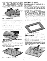
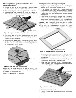
4. Using the part specifically marked for set-up, align the
reference mark with the centerline mark on the face of
the Domino.
5. Clamp the part in place using at least one hold-down. Larger
parts may require two hold-downs.
6. Slide the right-angle fence against the part, ensuring it is
also tight against the fixed fence. Lock the right-angle fence
in place using the wing knobs.
7. Cut the left mortise.
8. Replace the part with the next frame piece and proceed to
cut the left mortise in the end of the three remaining parts.
Right-Angle Fence
Spring Stop
Fixed Fence
Wing Knob
Insert Nut
Figure 10: Aligning the Domino to the fixed fences.
Hold-Down
T-Bolt
Keyhole Slot
Figure 11: Installing the hold-downs.
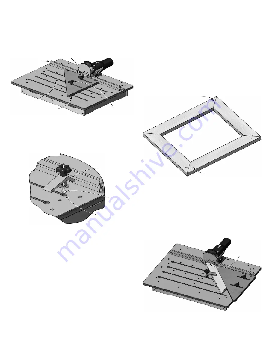
Figure 12: Example of a typical mitered frame. Note joint location
marks across each miter.
Joint Location Marks
Reference Mark
Figure 13: Cutting the first mortise.
Reference Mark
3


