


9. Once each part has the left end processed, place the offset
gauge in the hole in the right-angle fence and adjust the
gauge so the cursor registers against the inside surface of
the outermost spring stop on the front face of the Domino.
10. Lock this setting, and then remove the offset gauge from the
right-angle fence and set it aside.
Note:
While there are a number of features on the face of the
Domino that can be used for reference alignment, make it a habit
to consistently use the same reference point. In our example, our
reference point is the inside surface of the outermost spring stop
on the front face of the Domino.
11. Reposition the right-angle fence on the right side of the
Domino and place the offset gauge in the hole in the fence.
12. Slide the fence/gauge assembly until the cursor is aligned
with the inside surface of the outermost spring stop.
13. Ensure the right-angle fence is tight against the fixed fence.
Lock it in place using the wing knobs.
14. Remove the offset gauge.
15. Make a test cut with a scrap piece of the frame material to
ensure the set-up is correct and the desired mating right joint
alignment is achieved.
16. If all is correct, proceed to cut the right mortises in all the
parts. (If not, adjust as required.)
Cutting Mortises in Butt Joints
Butt-jointed frames require a bit more care than mitered joints as
far as marking the parts and being vigilant regarding “left” and
“right” ends of the part.
Note:
As with all joinery cut by machine, it is good practice to
have a number of extra parts to use for testing the set-up. This is
particularly important when configuring the joinery table for the
second half of the joint.
1. Cut all the parts of your project/frame to length.
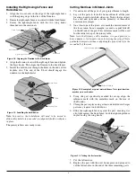
2. Lay out the parts to form the frame and mark all the joint
locations to indicate which side is up, as well as which edge
is out. In our example, we used a double line parallel to and
across the parts that will receive the mortises. On either
side of the mortise marks, we scribed a perpendicular line
extending to the outer edge of each part to indicate the outer
edge of the frame.
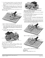
3. On at least one of the joints, also clearly mark where the
center of the mortise should be on that surface. In our
example, we used a capital letter R. This reference mark will
be used for the initial set-up of the joinery table.
4. Using the part specifically marked for set-up, align the
reference mark with the centerline mark on the face of
the Domino.
5. Ensure the part is tight against the fixed fence and clamp the
part in place with at least one hold-down.
6. Slide the right-angle fence against the end of the part that is
marked as the outside of the frame, ensuring it is also tight
against the fixed fence. Lock the right-angle fence in place
using the wing knobs.
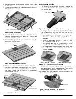
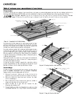
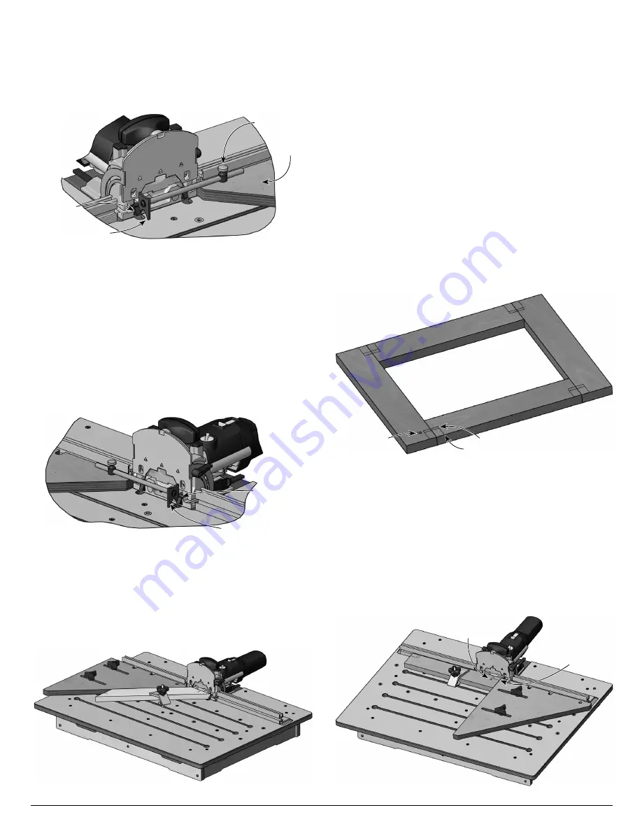
Figure 16: Cutting the mating Domino mortises.
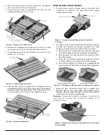
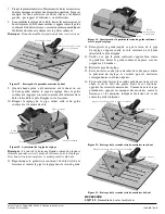
Figure 14: Setting the offset gauge.
Spring Stop
Offset Gauge
Cursor
Right-Angle
Fence
Figure 15: Reversing the right-angle fence and setting the mortise
distance with the offset gauge.
Outermost
Spring Stop
Cursor
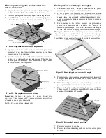
Figure 17: Butt-joint frame. Note the corner markings designate
which surface gets a mortise (two lines) and which surface is the
outside of the frame (one line).
Reference Mark
Mortise Mark
Outside Mark
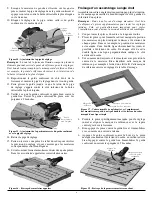
Figure 18: Cutting the first side-grain mortise.
Reference Mark
Outside mark against
the right-angle fence
4


