
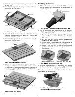

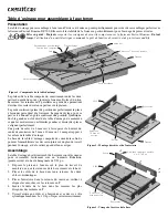

7. Cut the first mortise. Proceed to cut all the mortises that
are in a similar location. In our example, we cut the two
mortises that are in the side grain on the left-hand end of
the part.
8. Without changing the joinery table set-up, cut the two end-
grain mortises on the left-hand end of the part. Ensure that
the mark indicating the outside of the frame is in contact
with the right-angle fence.
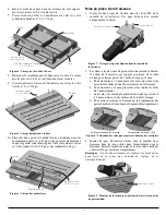
Note:
You will need to move the location of the hold-down, as we
did in our example.
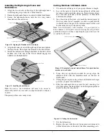
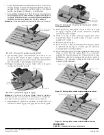
9. Once each part has one mortise cut in either the side
grain or the end grain, place the offset gauge in the hole
in the right-angle fence and adjust the gauge so the cursor
registers against one of the spring stops on the front face of
the Domino.
10. Lock this setting, and then remove the offset gauge from the
right-angle fence and set it aside.
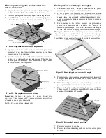
Note:
While there are a number of features on the face of the
Domino that can be used for reference alignment, make it a habit
to consistently use the same reference point.
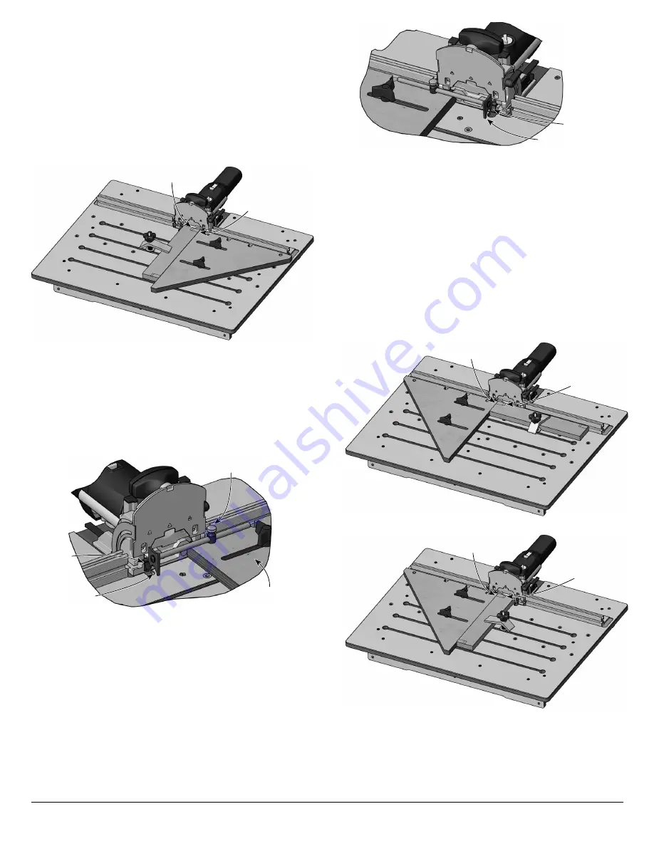
11. Reposition the right-angle fence on the right side of the
Domino and place the offset gauge in the hole in the right-
angle fence.
12. Slide the fence/gauge assembly until the cursor is aligned
with the opposite spring stop.
13. Ensure the right-angle fence is tight against the fixed fence.
Lock it in place using the wing knobs.
14. Remove the offset gauge.
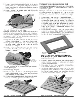
15. Make a test cut with a scrap piece of the frame material
to ensure the set-up is correct and the desired mating joint
alignment is achieved.
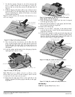
16. If all is correct, proceed to cut the second set of side-grain and
end-grain mortises. (If not, adjust as required.) As before, place
the parts such that the mortise mark is against the Domino and
the outer mark is against the right-angle fence.
Accessory
05J17.02
Optional Shim Pack, set of 6
Cursor
Offset Gauge
Spring Stop
Right-Angle Fence
Figure 20: Setting the offset gauge.
Figure 21: Repositioning the right-angle fence and setting the
mortise distance with the offset gauge.
Outermost
Spring Stop
Cursor
Figure 23: Cutting the second set of end-grain mortises.
End-Grain Mortise
Outside mark against
the right-angle fence
Figure 22: Cutting the second set of side-grain mortises.
Side-Grain Mortise
Outside mark against
the right-angle fence
Figure 19: Cutting the first end-grain mortise.
End-Grain Mortise
Outside mark against
the right-angle fence
Veritas Tools Inc. Ottawa ON K2H 1C2 Canada veritastools.com
© Veritas Tools Inc. 2022
1380 INS-780_B


