background image

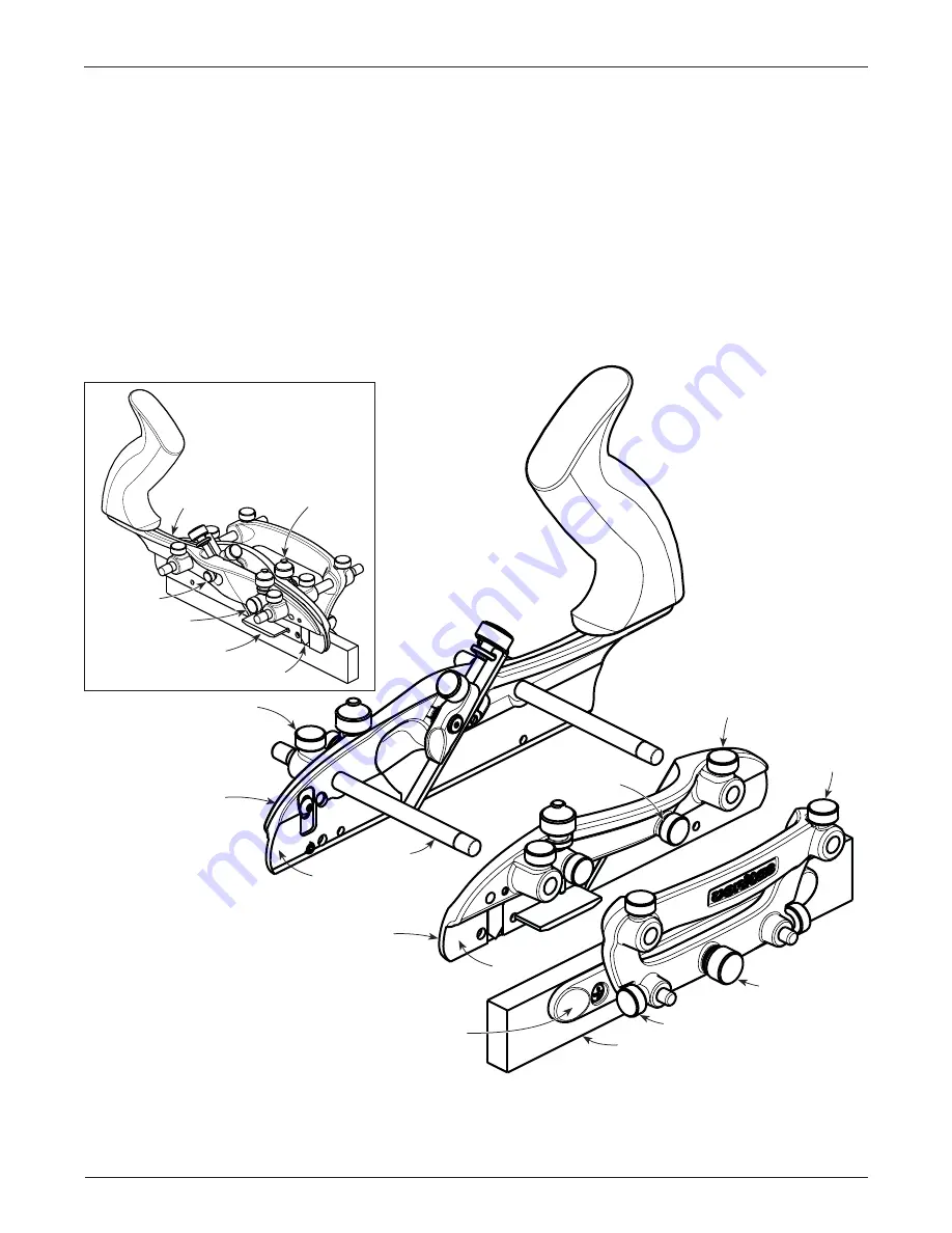
Figure 1: Plane components.

Micro-Adjust Knob

Fence Locking 

Knob

Sliding Section 

Locking Knob

Rod

Fence

Sliding Section

Body

Sub-Fence

Sub-Fence Locking Knob

Body Locking 

Knob

Blade Guide 

Knob

Skate

Skate

Depth Stop 

Fine-Adjust Knob

Small Blade 

Guide Knob

Body

Depth Stop

Depth Stop 

Locking Knob

Scoring Spur

2

Veritas

®

 Combination Plane

The Veritas

®

 Combination Plane can be used to tackle 

fundamental joinery, such as rabbets, tongues and 
grooves, as well as through-dadoes. It can also be used 
with beading, reeding and fl uting blades, individually 
or in sequence with others, to create a variety of 
decorative details.

The combination plane consists of three main parts: a 
body, a sliding section and a fence. The body includes 
the blade bed and depth adjustment, and the tote. The 
body and the sliding section have depth stops with a 
capacity of 

3

/

4

"

, scoring spurs for cross-grain work, and 

bevelled skates to permit the use of beading, reeding 
and fl uting blades. The sliding section rides on two rods 
and supports the outer edge of the blade. The fence also 
rides on the rods and, being symmetrical, the plane can 

Note:

 The fence section comes mounted upside down for shipping purposes. In use, it will need to be fl ipped 180°, 

as shown in 

Figure 1

.

To prevent racking, especially when reinstalling the fence, it is recommended that you stagger the fence rods; slide 
the fence onto one rod, then the other. Periodically lubricate the fence rods to keep the components sliding freely.

be set for right- or left-hand confi guration to suit your 
dominant hand or accommodate grain direction. The 
fence assembly includes a wooden sub-fence with a 
micro-adjust knob. Two pairs of rods are included, 
5

"

 long and 8

"

 long, letting you make cuts reaching up to 5

"


from the edge of the workpiece.  Large brass knobs make 
adjustments fast and easy without need for tools, and the 
large torrefi ed maple tote offers a solid, comfortable grip. 
A straight 

1

/

4

"

 wide lapped A2 tool steel blade is included, 

and a selection of other blades is available separately. It 
will accept the right-hand (and unhanded) blades available 
with the Veritas Small Plow Plane, as well as the blades 
used with the Stanley #45 and most of those used with the 
Stanley #55.

Summary of Contents for 05P59.01

Page 1: ...05P59 01 Combination Plane ...

Page 2: ...and supports the outer edge of the blade The fence also rides on the rods and being symmetrical the plane can Note The fence section comes mounted upside down for shipping purposes In use it will need to be flipped 180 as shown in Figure 1 To prevent racking especially when reinstalling the fence it is recommended that you stagger the fence rods slide the fence onto one rod then the other Periodica...

Page 3: ...skate as is the case with the body as shown in Figure 3 Tighten the locking knobs on the sliding section Whenusingnarrowblades theslidingsectionisremoved essentially converting the combination plane into a small plow plane In this use the small blade guide knob see Figure 1 inset is installed in the threaded hole in the machined bed side as shown in Figure 4 The small blade guide knob will not onl...

Page 4: ...coring spur as shown in Figure 7 The spur retention screw locks the spur into position and the spur adjustment screw sets how far the spur protrudes from the face of the skates To deploy the scoring spur s loosen the spur retention screw and lower the spur slightly below the skate to a maximum of 1 32 and then tighten the retention screw to lock the spur s position Adjust the amount of protrusion ...

Page 5: ...3 Position the fence to locate the tongue at the desired distance from the edge of the board Cutting Beads For cutting small beads 1 8 to 1 4 remove the sliding section and use the small blade guide knob to support the blade For larger beads 5 16 to 1 2 use the sliding section to support the outer edge of the blade as shown in Figure 10 Note A 1 16 quirk is cut on either side of each bead 1 Instal...

Page 6: ...he fence to establish the width of the rabbet from the edge of the workpiece 4 Set the depth stop on the body to determine the resulting depth of the rabbet below the surface of the workpiece Cutting Flutes For cutting flutes remove the sliding section and use the small blade guide knob to support the blade The fluting blade is offset and will be centered on the body skate 1 Install the fluting blad...

Page 7: ... Blade Sharpening The blades used with the combination plane come with the face lapped and are ground with a 35 bevel Since the blade is installed bevel down the cutting angle is determined by the bed angle in this case 45 Additional sharpening need only involve honing a small micro bevel The standard grooving blades and the tongue cutting blades are made of A2 tool steel The rabbeting beading ree...

Page 8: ...A2 05P51 42 12mm Wide Blade 05P51 46 16mm Wide Blade 05P51 48 18mm Wide Blade 05P51 70 Set of 3 Metric Blades 05P51 87 11 16 Rabbeting Blade PM V11 Tongue Cutting Blades Imperial A2 05P51 62 1 8 Tongue Cutting Blade 05P51 63 3 16 Tongue Cutting Blade 05P51 64 1 4 Tongue Cutting Blade 05P51 95 Set of 3 Imperial Blades Tongue Cutting Blades Metric A2 05P51 65 4mm Tongue Cutting Blade 05P51 66 5mm To...

Reviews: