Connecting the network cables
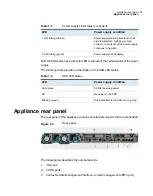
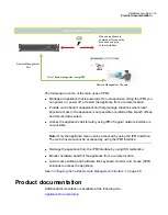
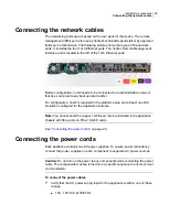
The networking ports are accessed on the rear panel of the device. The remote
management (IPMI) port is for use by Veritas Technical Support staff or by approved
field service technicians. The following picture shows the layout of the network
ports. It includes the four 1 Gb Ethernet ports. The Veritas Remote Management
Interface port is located to the left of the 1 Gb Ethernet ports.
Before configuration, host0 needs to be connected to an administrative network
that does not provide any backup data transfer.
For configuration, host0 is required for the platform setup and at least one NIC
should be configured for the application instance.
Note:
You cannot bond the copper 1 GbE port that are installed in the appliance
chassis with fibre ports on PCIe 10-GbE cards.
See
on page 26.
Connecting the power cords
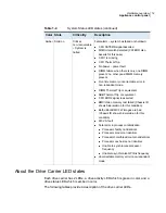
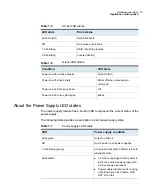
Each appliance contains two AC power supplies. To ensure power redundancy,
connect the power supplies on each component to separate AC power sources.
Caution:
Do not turn on the power to any components while connecting the power
cords. The components must be turned on in a specific sequence to ensure correct
communication.
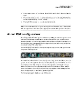
To connect the power cables
1
Verify that the AC power supply input for the appliance is within one of these
ranges.
■
100 - 127 VAC at 50/60 Hz
26
Installation procedures
Connecting the network cables

