030-300505 Rev. A
9
April 2007
User Guide
VersaLink Wireless Gateway (Model 327W)
5.2
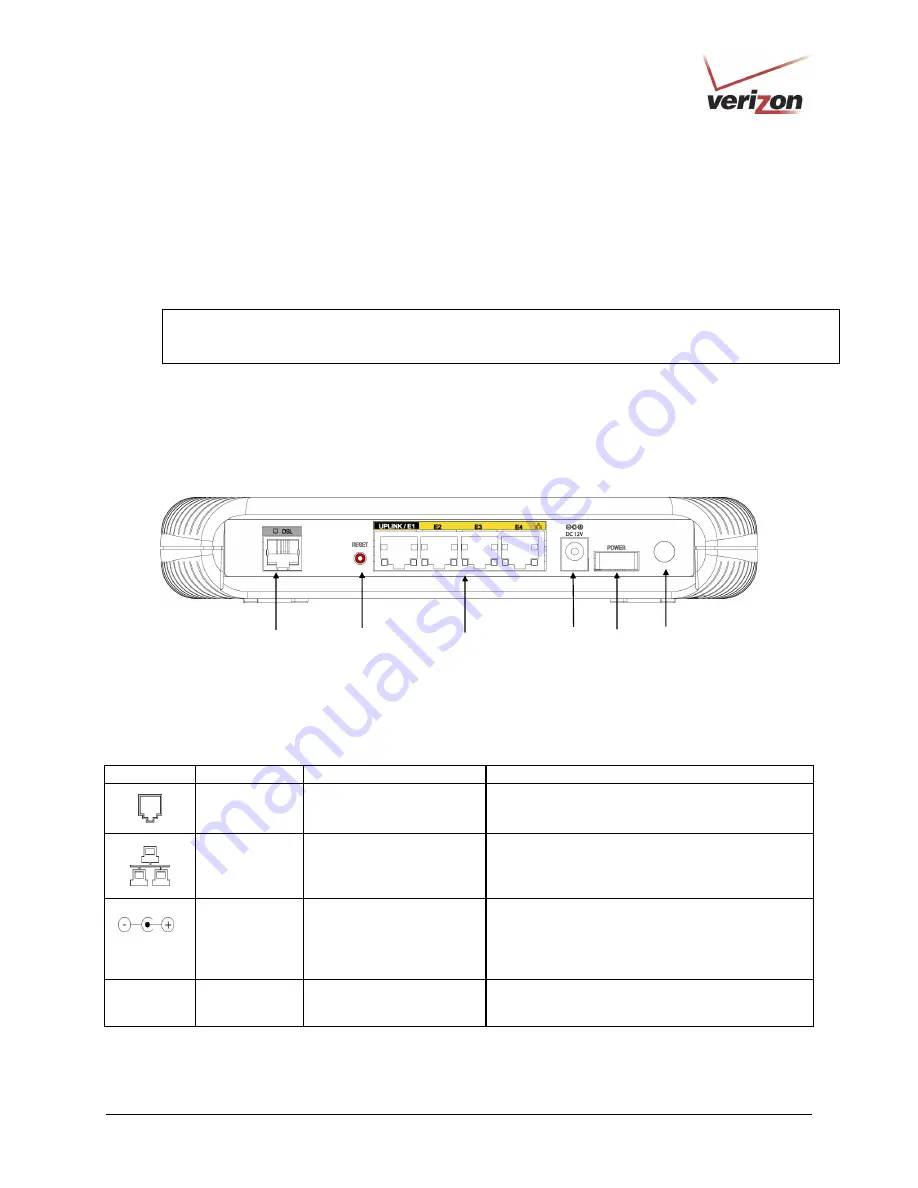
Cable Connectors and Switch Locations
•
DSL connector (RJ-11)
•
Reset push button
•
(4) Ethernet connectors (RJ-45) optional uplink port
•
(4) Ethernet connector (RJ-45) with optional UPLINK/E1 uplink port
NOTE:
When using the optional UPLINK/E1 jack (when VersaLink is configured for WAN Uplink mode),
Ethernet LAN connection is limited to ports E2, E3, and E4. The Uplink feature is optional. If Uplink is not
enabled via the Web pages, VersaLink will use DSL as the WAN interface.
•
Power connector (DC 12V) barrel
•
OFF/ON power switch
•
Wireless 802.11b/g SMA connector and antenna
VersaLink Gateway - Rear View
5.3
Connector Descriptions
The following chart displays the Router’s connector types.
SYMBOL
N
AME
T
YPE
F
UNCTION
DSL LINE
6-pin (RJ-11) modular jack
Connects to an ADSL-equipped telephone jack or
to the DSL connection of a POTS splitter.
ETHERNET
8-pin (RJ-45) modular jack
Connects the 10/100 Base-T Ethernet device to a
PC or Hub.
DC 12V
POWER Barrel
connector
Connects the DC 12V power connector to an AC
wall jack.
Wireless
Antenna
SMA connector and
antenna
Connects via wireless 802.11 b/g
DSL Line
Connector
Off/On
Power Switch
Power
Connector
Ethernet Connectors
(UPLINK/E1 through E4)
Reset
Button
Wireless Antenna
Connector


