EUROBLOC
SERVICE MANUAL FOR HOIST
100/212
This document and the information contained herein, is the exclusive property of Verlinde S.A.S. and represents a non-public, confidential and proprietary trade secret that
may not be reproduced, disclosed to third parties, altered or otherwise employed in any manner whatsoever without the express written consent of Verlinde S.A.S.
Copyright © (2013) Verlinde S.A.S. All rights reserved.
06/2015
5
6
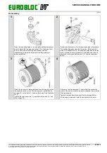
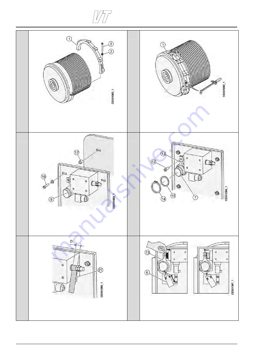
Clean the rope drum holding brake surface thoroughly. Install
the brake rim (1) halves on the drum groove. Install the disc
springs (2) on the bolts (3) and screw the bolt into the brake
rim (1).
Tighten the two brake rims (1) together with the bolt (3) and
disc springs (2).
If there are two brake bands (1) ensure that the connection
points of the halves of both rims is not aligned, they must be
90 degrees apart.
Tighten the brake band bolts evenly with a torque 60 Nm.
7
8
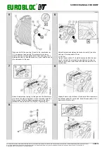
Install the solenoid assembly (8) to the attachment plate.
Install the attachment plate to the drum end plate with bolts
(16) and washer and place bushings (17) on the bolts between
the attachment plate and the end plate. Tighten the bolts
lightly.
Place the snap ring to its place to the second groove on the
axle (7).Place one 2 mm washer and one 1 mm washer on the
axle (7).Place the lever (13) on the axle (7) and washer (15)
on the axle (7) and lock it in place with a snap ring (14).Insert
the lever (13) into the solenoid shaft groove and lock them
together with bolt (12) and nuts.
9
10
Adjust the solenoid stroke to 16 mm. Do this with the help of
the same width steel band (27).
D = 16 mm.
Press the solenoid shaft in so that the latch is in open position.
Adjust the limit switch (6) so that it is in open position. Release
the solenoid shaft. The switching point must be just before the
limit switch roller reaches the topmost part of the cam on the
lever (13).

