EUROBLOC
SERVICE MANUAL FOR HOIST
101/212
This document and the information contained herein, is the exclusive property of Verlinde S.A.S. and represents a non-public, confidential and proprietary trade secret that
may not be reproduced, disclosed to third parties, altered or otherwise employed in any manner whatsoever without the express written consent of Verlinde S.A.S.
Copyright © (2013) Verlinde S.A.S. All rights reserved.
06/2015
11
12
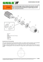
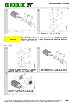
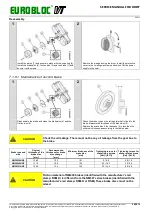
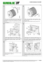
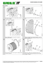
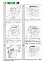
Lock the solenoid (8) in open position with the steel band (27)
used earlier for the test run and rope reeving.
Attach the cover (10) to the attachment plate with three bolts
(9) and washers. Tighten with a torque 6 Nm.
Attach the limit switch wire with a cable tie to the hoist end
plate for the final electrification.
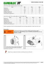
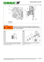
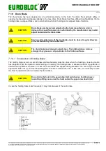
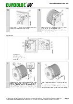
Adjustment
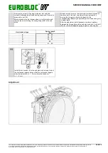
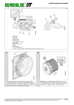
4. Detent arm
5. Teeth of brake rim
7. Shaft of the detent arm
6. Holding brake limit switch
8. Solenoid
1
2
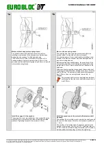
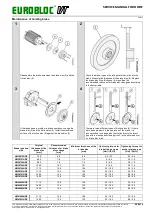
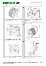
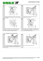
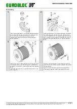
Assemble the brake rims (1) together with disc springs (2) and
screws (3). Adjust the rims (1) so that there is a difference of
5 mm (0.2”) between the teeth (5) of the two brake rims (1).
The 5 mm difference is to allow one rim to begin the braking
before the second rim engages to reduce the dynamic impact.
Tighten the brake rim screws (3) to a torque of 60 Nm (44 ft
lb).
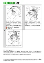
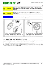
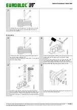
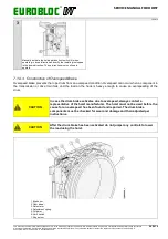
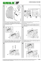
Check with the caliper that the gap between the brake rim
halves (1) is the same on both sides. This is to ensure the
even tooth to tooth distances over the brake rim connection.


