EUROBLOC
SERVICE MANUAL FOR HOIST
108/212
This document and the information contained herein, is the exclusive property of Verlinde S.A.S. and represents a non-public, confidential and proprietary trade secret that
may not be reproduced, disclosed to third parties, altered or otherwise employed in any manner whatsoever without the express written consent of Verlinde S.A.S.
Copyright © (2013) Verlinde S.A.S. All rights reserved.
06/2015
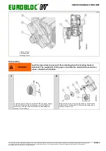
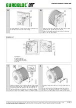
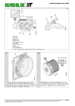
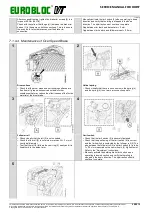
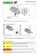
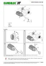
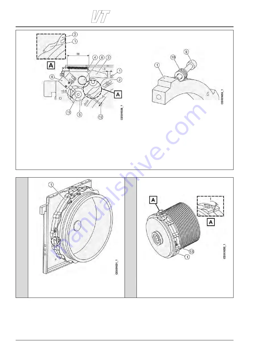
1. Brake rim
2. Cam wheel
3. Detent arm
4. Helical spring
5. Follower roll
6. Over speed limit switch
7. Rope drum
8. Shaft of detent arm
9. Screw
10. Disc springs
11. Roll for limit switch
12. Only in models with drum diameter 608 mm with two hoisting motors
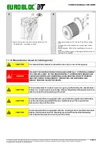
1
2
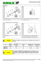
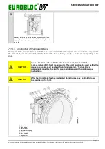
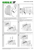
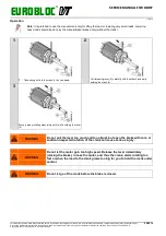
In the two brake rim model, the connection points of the
halves of both rims (1) must not be aligned, they must be
90 degrees apart. The 90 degrees placement is to reduce the
risk of having two bolt connection teeth being contacted by the
detent arm when an overspeed braking occurs.
Adjust the rims (1) so that there is a difference of t = 5 mm
(0.2”) between the teeth (13) of the two brake rims (1). The
5 mm difference is to allow one rim to begin the braking before
the second rim engages to reduce the dynamic impact.

