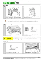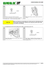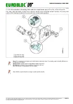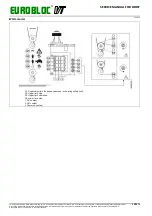
EUROBLOC
SERVICE MANUAL FOR HOIST
115/212
This document and the information contained herein, is the exclusive property of Verlinde S.A.S. and represents a non-public, confidential and proprietary trade secret that
may not be reproduced, disclosed to third parties, altered or otherwise employed in any manner whatsoever without the express written consent of Verlinde S.A.S.
Copyright © (2013) Verlinde S.A.S. All rights reserved.
06/2015
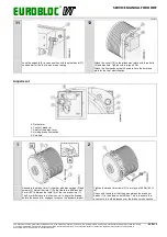
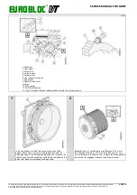
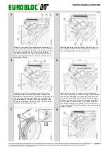
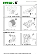
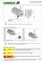
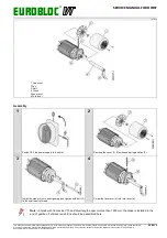
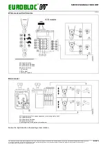
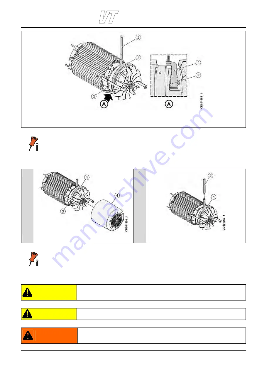
1. Fork lever (assembled to hoisting motor brake)
2. Lever arm
3. Brake frame
A. Gap (X), (>1.8 mm)
Note: Gap (X) between fork lever (1) and brake frame (3) must be at least 1.8 mm.
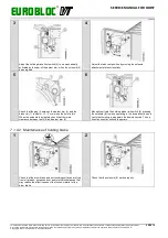
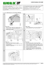
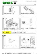
Assembling the manual brake release
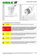
1
2
Remove the fan cover (4) off the motor. Ensure that the fork
lever (1) can move freely.
Screw the lever arm (2) into fork lever (1).
Note: In hoists with frame size VT3 and drum length equal or more than 1250 mm, the brake is installed in the
end of gearbox. Fork lever and crank should be assembled here.
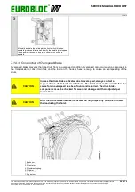
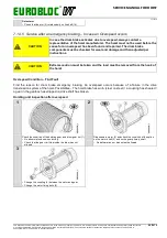
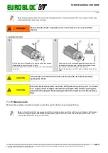
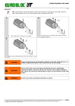
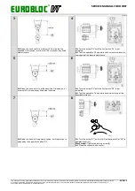
Brake release usage instructions
CAUTION
Secure the area under and around the hoist. Warn the personnel on the shop
floor and the supervisors about the intended action.
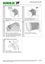
CAUTION
Ensure that the area under the hoist is free of obstacles.
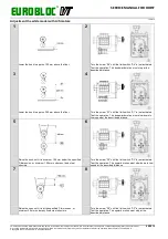
WARNING
Beware that the motor rotational speed does not exceed the rated rotational
speed.

