EUROBLOC
SERVICE MANUAL FOR HOIST
172/212
This document and the information contained herein, is the exclusive property of Verlinde S.A.S. and represents a non-public, confidential and proprietary trade secret that
may not be reproduced, disclosed to third parties, altered or otherwise employed in any manner whatsoever without the express written consent of Verlinde S.A.S.
Copyright © (2013) Verlinde S.A.S. All rights reserved.
06/2015
A
B
E
D
B
C
D
E
d1
g1
b2
b1
a
3
h
2
a1
b
1
b2
b3
b4
h3
h4
h1
e
3
a2
l1
b
3
a2
g1
f1
Ball
r2
a
1
l1
e
3
a
3
h
2
f1
Ba
ll r2
c_hb1b
RSN
HBC
d1
RSN (DIN 15401) /RFN
HBC
RSN 1 RSN 1.6 RSN 2.5 RSN 4
RSN 5
RSN 6
RSN 10 RSN 16 RFN 20 RFN 25 HBC 1.6 HBC 2.5
HBC 5
a
2
40..43
45…48
50…53
56…60
63…67
71…76
90…96
112...
118
125…
137
140…
152
45…48
51…54
63…66
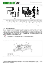
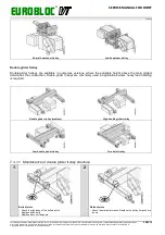
Note: Safety latch decreases dimension a
2
about 5 mm on HBC forging and about 15 mm on RSN forging.
7.2.8 Overload protection
The overload protection prevents hoisting motion when there is an excessive load. The operating point of overload
protection is stated in the written records for the test drive of the hoist. Overload protection is achieved by either a
mechanical switch or an electronic load sensor. The mechanical switch is connected to the hoisting circuitry, and
controls the hoisting contactor. The load sensor is connected to a separate condition-monitoring unit. The condition
monitoring unit prevents hoisting motion when there is an excessive load. The overload protectors with a load
sensor are equipped with an extra safety limit-switch.
Note: From year 2015, models with strain gauge do not contain a safety limit switch.
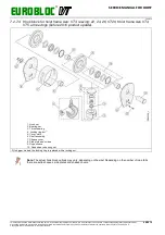
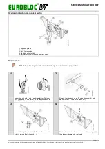
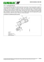
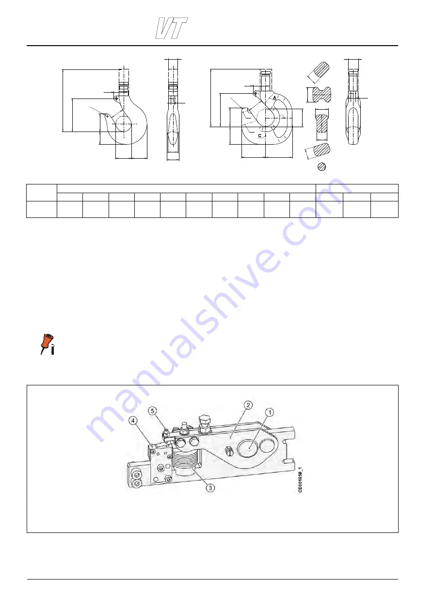
Overload device, mechanical switch, hoist frame size: VTs.
1. Rope anchorage
2. Lever mechanism
3. Set of plate springs
4. Mechanical limit switch
5. Adjustment screw for mechanical limit switch

