EUROBLOC
SERVICE MANUAL FOR HOIST
209/212
This document and the information contained herein, is the exclusive property of Verlinde S.A.S. and represents a non-public, confidential and proprietary trade secret that
may not be reproduced, disclosed to third parties, altered or otherwise employed in any manner whatsoever without the express written consent of Verlinde S.A.S.
Copyright © (2013) Verlinde S.A.S. All rights reserved.
06/2015
7.4.4 Cubicles and wiring
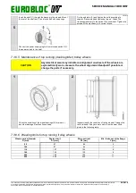
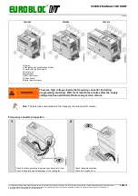
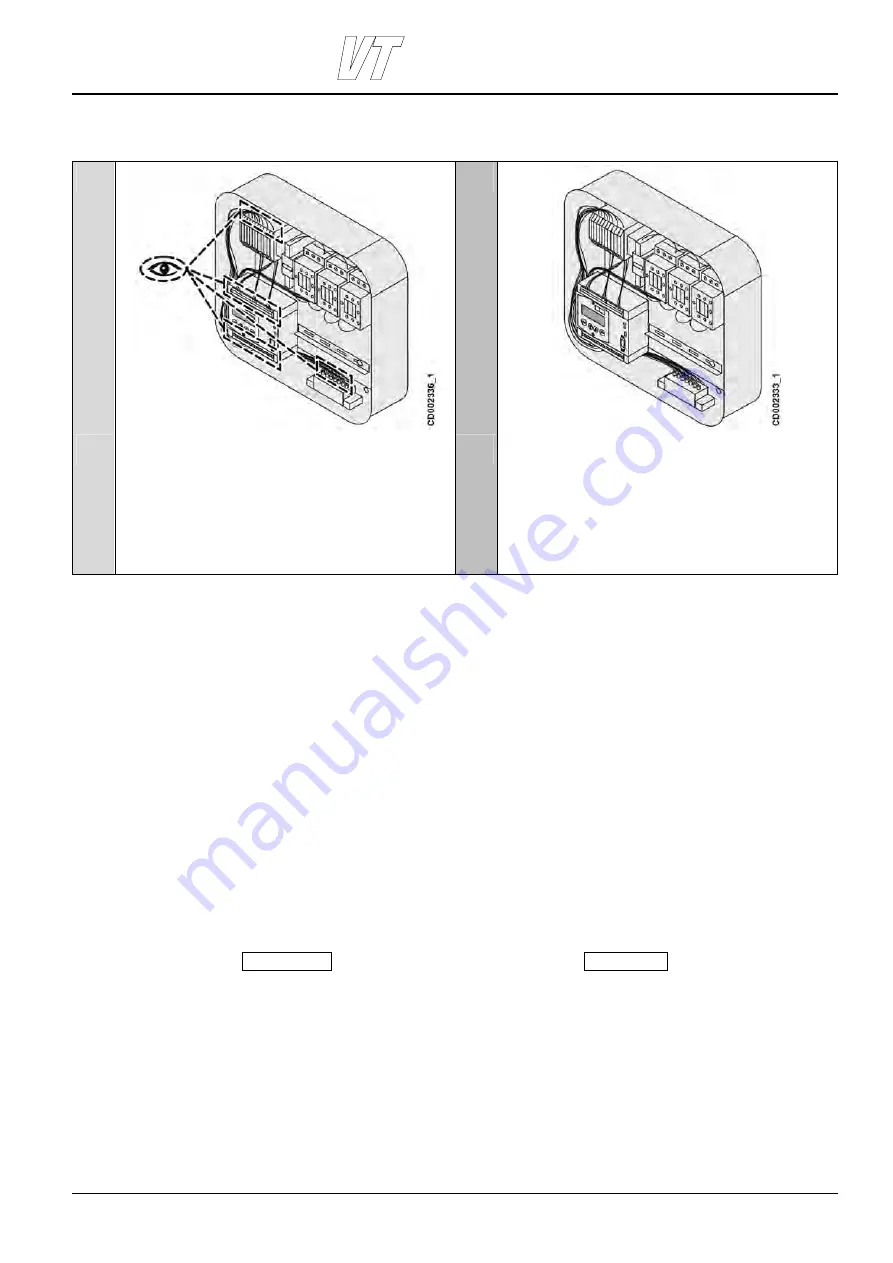
Inspection of cubicles and wiring
1
2
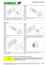
Open electric cubicles and check visually the fastenings of the
electrical equipment and internal wiring connections.
Check the security of the fastenings in the electrical cubicle.
Follow the power supply and visually check potential areas for
crushing.
Check visually or test by hand that cable bushings are tight.
Check visually or test by hand that connectors are OK.
Check the cableways for electrical wiring. Make sure that
wires do not snag on structures when the hoist and trolley are
in motion.
Check that the connections of electrical devices comply with
the wiring diagrams and meet local requirements.
7.4.5 Contactors
Hoisting, speed change, and brake contactors are monitored by CID that calculates contactors’ lifetime, that is, the
number of the control actions. The maximum number of control actions is defined with Parameter 6-19 (Max
Control). The default value is 640,000 operations. Once this design limit has been reached, CID sends a warning:
“Control”, and the contactors must be replaced. If a brake contactor contains an auxiliary contact block or a time
delay auxiliary contact block, replace that part as well.
7.4.5.1 CID parameter settings after replacing contactors
When the condition monitoring unit indicates the “Control” warning, one of the start counters 2-7 (ST up), 2-8 (ST
down) or 2-9 (ST fast), has reached the set design limit (the default value is 640,000 operations) which is defined
with parameter 6-19 (Max Control). Replace the contactors and calculate a new parameter value for parameter 6-
19 (Max Control) in CID as follows:
Calculate a new value for parameter 6-19 (Max Control) by taking the maximum (value) of the parameters 2-7 (ST
Up), 2-8 (ST down) or 2-9 (ST Fast) increased by 640k0 (640 000).
Max (2-7, 2-
8, 2-9)
6-19
+
640k0
=
Example:
A warning when parameter 6-19=640k0 and the start counters show the following values:
Parameter 2-7=630k0
Parameter 2-8=470k0
Parameter 2-9=739k0
The new value of parameter 6-19 = Max(2-7,2-8,2-9)+640k0 =739k0+640k0=1M379.

