EUROBLOC
SERVICE MANUAL FOR HOIST
26/212
This document and the information contained herein, is the exclusive property of Verlinde S.A.S. and represents a non-public, confidential and proprietary trade secret that
may not be reproduced, disclosed to third parties, altered or otherwise employed in any manner whatsoever without the express written consent of Verlinde S.A.S.
Copyright © (2013) Verlinde S.A.S. All rights reserved.
06/2015
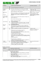
Component
In
te
rv
a
l
Inspection and maintenance task
Interval is SWP% reduction or calendar months
See further instructions
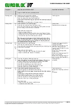
Hoisting limit
switches
Up Limit
Slow Down Up
Limit
Down Limit
Hook limit (Safety
Up Limit/ Ultimate
Limit)
10%
12
Verify the condition and operation of hoisting limit switches.
Operate the hoist in the up direction and slowly drive to the Up Limit
Switch Activation point. Check that it works.
Run the hook block down at a short distance and drive at high speed
and check if the Slow Down Up Limit activates to override the high-
speed command to slow down the speed before the Up Limit
activates.
Operate the hoist in the down direction and drive to the Down Limit
Switch Activation point.
Test the Hook Limit by hand actuation.
Adjust or replace parts as required.
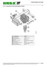
Construction of hoisting limit switch for
hoist frame size: VTs
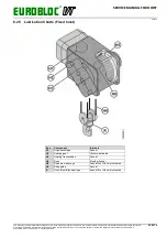
Construction of hoisting limit switch for
hoist frame size: VT1, VT2, VT3, VT4,
VT5
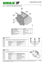
Maintenance task for hoisting limit
switch, hoist frame size: VTs
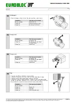
Maintenance task for hoisting limit
switch, hoist frame size: VT1, VT2,
VT3, VT4, VT5
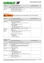
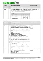
Up Limit Distance
10%
12
Verify Up Limit Distance.
Verify the Up Limit Distance to the frame of the trolley. It is important
to adjust the C dimension according to the specification, to minimize
rope and sheave wear.
Down Limit
Distance
10%
12
Verify Down Limit Distance.
When the hook block is in the Down Limit Switch Activation point,
verify that there is a minimum number of wraps of rope on the drum
according to the standards (the absolute minimum is two full turns of a
rope).
Overload
protector
10%
12
Inspect the condition and operation of the overload protector.
Mechanical switch and load sensor overload device:
Test the free movements of mechanical parts.
Test the mechanical overload limit switch by mechanically activating
the switch and checking for a click.
Clean and lubricate lever mechanism.
Verify that the set screw is locked in its place.
When required to confirm calibration, place a test weight of a nominal
load plus 10%. Adjust mechanical overload to stop hoisting at 110% of
capacity.
Replace damaged parts.
Power measurement overload device:
Conduct a test operation of the power measurement overload device
according to the local regulations if necessary.
Overload protection
Maintenance of overload device
Operation test of overload
Condition
monitoring unit
10%
12
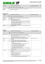
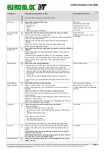
Verify the operation of the condition monitoring unit.
Test the condition monitoring unit by lifting a known load and verify
that the unit reads the load within 5% accuracy. If not reading
properly, a new calibration of the unit required.
Check for possible error codes and warnings.
Service manual for hoist control
device
Runway mechanical
Component
In
te
rv
a
l
Inspection and maintenance task
Interval is SWP% reduction or calendar months
See further instructions
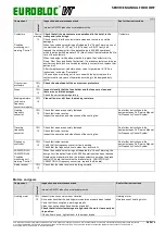
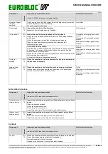
Crane runway rail
Inspect the crane runway rail.
• Check the bridge squareness
• Check that both end trucks are working simultaneously in the starting
and the stopping phases
• Monitor for possible sounds of grinding or any unsmooth travel of the
bridge along the runway
• Visually check the straightness
• Check rail fastenings randomly for possible loose connections
• Check the rail for any signs of wear.

