EUROBLOC
SERVICE MANUAL FOR HOIST
52/212
This document and the information contained herein, is the exclusive property of Verlinde S.A.S. and represents a non-public, confidential and proprietary trade secret that
may not be reproduced, disclosed to third parties, altered or otherwise employed in any manner whatsoever without the express written consent of Verlinde S.A.S.
Copyright © (2013) Verlinde S.A.S. All rights reserved.
06/2015
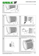
4
5
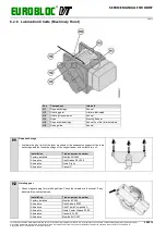
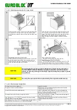
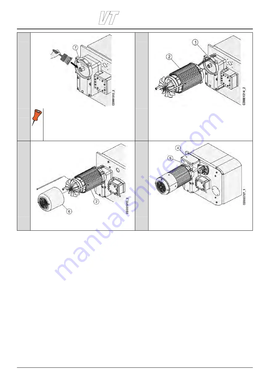
Install and grease the gear rim and coupling (7)
thoroughly on the reducer gear shaft.
A coupling that has a groove outside MUST be
installed with the groove facing the gear.
Couplings in some gears of bigger size do not have
any groove outside and they can be installed in both
ways.
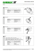
Lift the hoisting motor (2) and align motor shaft with the
coupling. Pass the motor power cables through the hole in the
hoisting gear (1).
6
7
Install the hoisting motor (2) with screws. Tighten the screws
to the recommended torque. Reassemble the fan cover (6)
and screws.
Connect the motor cabling and install the junction box (4).
Install the hoisting limit switch assembly (5) and place the limit
switch assembly cover box.

