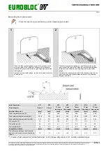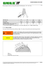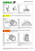
EUROBLOC
SERVICE MANUAL FOR HOIST
61/212
This document and the information contained herein, is the exclusive property of Verlinde S.A.S. and represents a non-public, confidential and proprietary trade secret that
may not be reproduced, disclosed to third parties, altered or otherwise employed in any manner whatsoever without the express written consent of Verlinde S.A.S.
Copyright © (2013) Verlinde S.A.S. All rights reserved.
06/2015
5
6
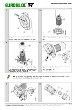
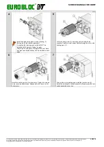
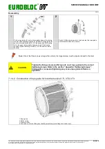
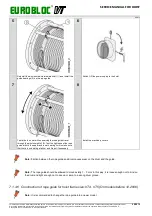
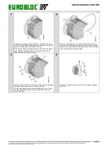
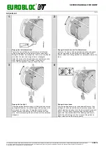
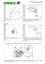
Switch ON the power supply to the hoist.
Test the rope guide for smooth operation by running the hoist
both directions. Install the machinery covers.
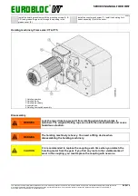
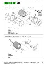
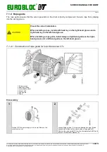
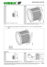
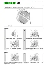
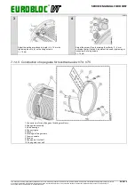
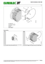
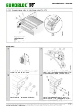
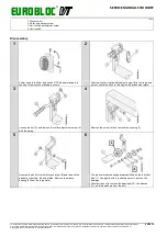
7.1.4.3 Construction of rope guide for hoist frame size: VT1, VT2, VT3 (On models before
2008)
1. Rope guide
2. Roller spring
3. Roller axle
4. Pressure roller
5. Connector rod for end flanges of hoisting machinery (drum flange connector rod)
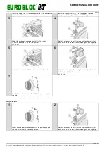
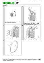
Disassembly
1
2
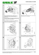
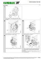
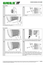
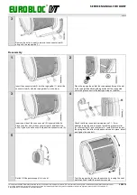
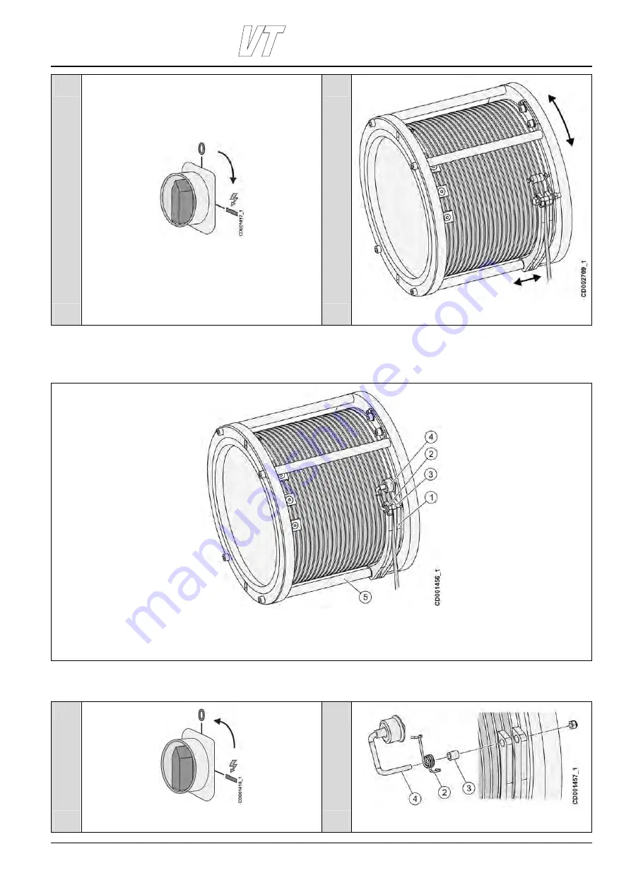
Switch OFF the power to the hoist, lower the hook to the
ground and remove the machinery covers.
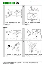
Remove the nut and then remove the roller (4), roller spring
(2), and roller axle (3).

