EUROBLOC
SERVICE MANUAL FOR HOIST
65/212
This document and the information contained herein, is the exclusive property of Verlinde S.A.S. and represents a non-public, confidential and proprietary trade secret that
may not be reproduced, disclosed to third parties, altered or otherwise employed in any manner whatsoever without the express written consent of Verlinde S.A.S.
Copyright © (2013) Verlinde S.A.S. All rights reserved.
06/2015
3
4
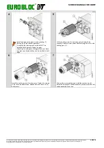
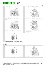
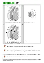
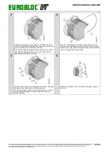
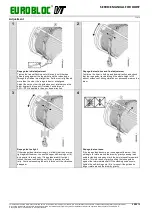
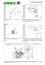
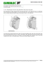
Adjust the spring pre-stress to length (L) = 14 mm by
tightening the nuts (4) on the fixing screws.
L = 14 mm
Adjust the screw (3) so the raising the roller by 3…4 mm
activates the limit switch. Adjustment is done by tightening or
loosening the fixing screws.
L = 14 mm
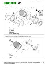
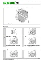
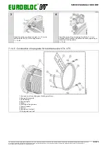
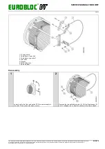
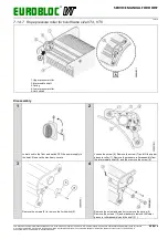
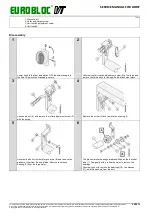
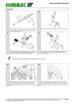
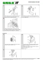
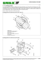
7.1.4.5 Construction of rope guide for hoist frame size: VT4, VT5.
1. Connector rod for end flanges of hoisting machinery
2. Rope guide assembly
3. Guide bearings
4. Rope exit gate
5. Spacer
6. Locking bar fixing screws
7. Tension screws
8. Springs
9. Rope guide, front half
10. Rope guide, rear half

