EUROBLOC
SERVICE MANUAL FOR HOIST
75/212
This document and the information contained herein, is the exclusive property of Verlinde S.A.S. and represents a non-public, confidential and proprietary trade secret that
may not be reproduced, disclosed to third parties, altered or otherwise employed in any manner whatsoever without the express written consent of Verlinde S.A.S.
Copyright © (2013) Verlinde S.A.S. All rights reserved.
06/2015
5
6
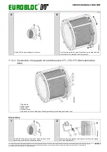
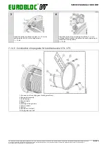
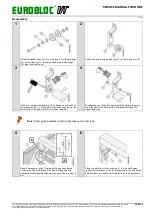
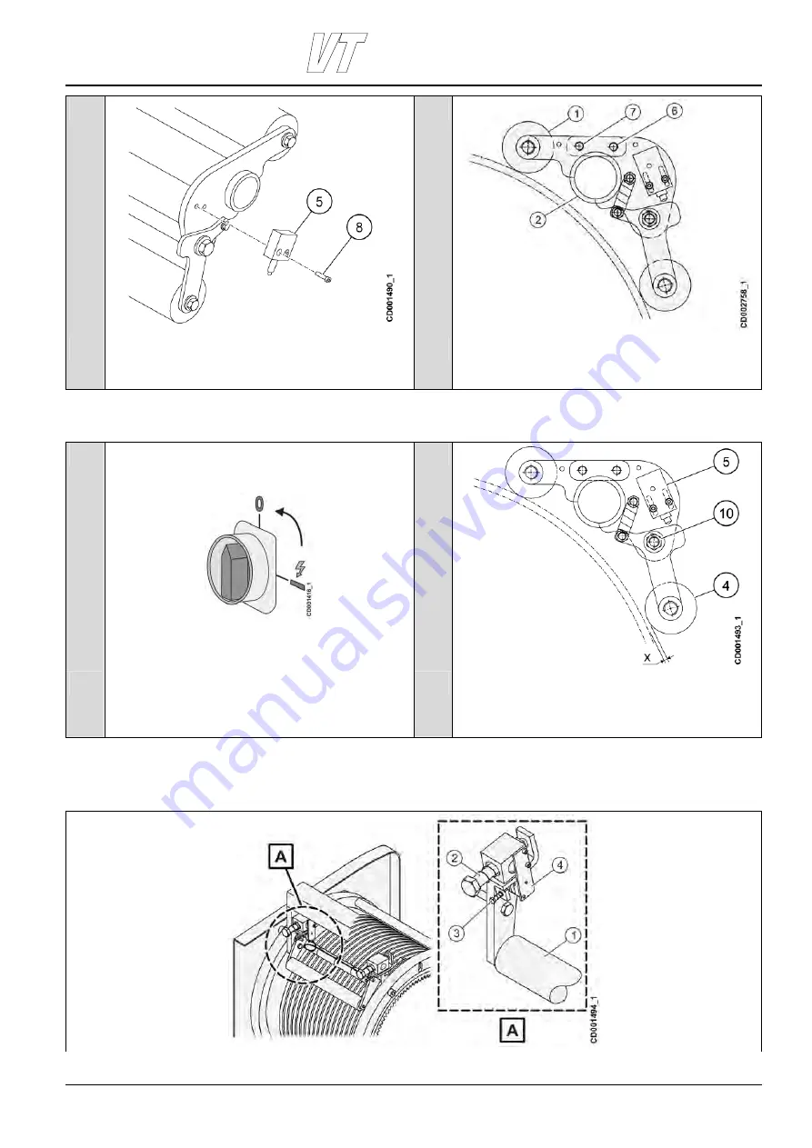
Install the limit switch (5) to the pressure roller assembly with
the screws (8).
Install the screw (6) lightly without tightening. Tilt the upper
pressure roller (1) and place the assembly over the
intermediate shaft (2). Install the screw (7). Tighten both
screws (6) and (7).
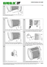
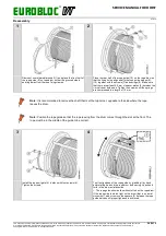
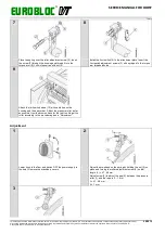
Adjustment
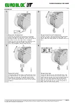
1
2
Lower the hook to the floor and switch OFF the power supply
to the hoist. Remove the machinery covers.
Loosen the screw (1+) and adjust the roller (4) so that there is
a gap of x = 1…2 mm between the roller and the rope. Tighten
the screw (10). Adjust the limit switch (5) so that if pressure
roller (4) rises 4 mm from top surface of rope the limit switch
activates.
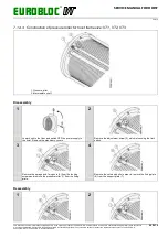
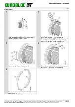
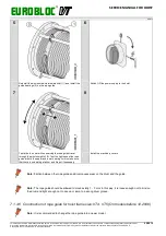
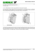
7.1.4.8 Construction of rope pressure roller for hoist frame size VT4, VT5(On models before
2011)

