EUROBLOC
SERVICE MANUAL FOR HOIST
88/212
This document and the information contained herein, is the exclusive property of Verlinde S.A.S. and represents a non-public, confidential and proprietary trade secret that
may not be reproduced, disclosed to third parties, altered or otherwise employed in any manner whatsoever without the express written consent of Verlinde S.A.S.
Copyright © (2013) Verlinde S.A.S. All rights reserved.
06/2015
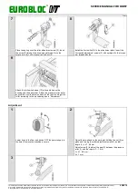
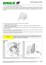
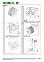
1a
1b
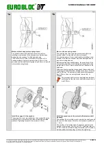
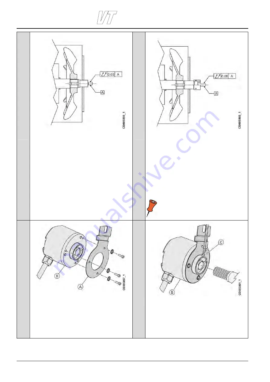
Motors without a separate coupling sleeve:
You should measure the shaft end eccentricity before
installing a new encoder if the previous encoder has been
damaged and no reason for the damage known.
The eccentricity (A) of the rotor surface in relation to the
bearing surfaces must not be greater than 0.03mm. If the
eccentricity of the shaft end is greater than 0.03mm, the shaft
rotor must be straightened.
Motors with a coupling sleeve:
The coupling sleeve becomes an extension shaft for the
encoder when it is mounted onto the motor shaft.
You should measure the eccentricity before installing a new
encoder if the previous encoder has been damaged and no
reason for damage known.
Before mounting the coupling sleeve, the eccentricity of the
rotor surface in relation to the bearing surfaces must not be
greater than 0.03mm. Same eccentricity limit applies for the
shaft end.
After mounting the coupling sleeve, check the eccentricity of
this extension shaft. Maximum allowed eccentricity (A) for the
shaft is 0.05mm. If the extension shaft eccentricity is greater
than 0.05mm, it has to be straightened, remounted, or
changed.
The extension shaft must not be straightened without
confirming first that the motor shaft end eccentricity is
max 0.03mm.
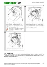
2
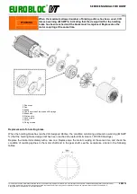
3
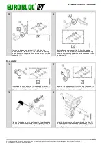
Install the support to the encoder.
The support (A) is not pre-installed on the encoder (B) by the
manufacturer. It is mounted with three screws and serrated
washers. Tightening torque for the screws is 2.5 Nm.
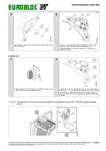
Install the encoder onto the motor shaft/extension shaft
manually.
The encoder (B) is installed in such way that the shaft goes all
the way into the encoder. After this, the encoder is pulled out
1…2 mm.
The encoder is firmly attached to the shaft by tightening the
encoder collar screws (C) with key SW2. Tightening torque is
1.5 Nm. Use also a thread-locking compound (soft or medium,
which enables also reopening) to secure the tightening.

