EUROBLOC
SERVICE MANUAL FOR HOIST
89/212
This document and the information contained herein, is the exclusive property of Verlinde S.A.S. and represents a non-public, confidential and proprietary trade secret that
may not be reproduced, disclosed to third parties, altered or otherwise employed in any manner whatsoever without the express written consent of Verlinde S.A.S.
Copyright © (2013) Verlinde S.A.S. All rights reserved.
06/2015
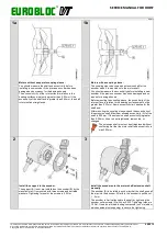
4
5a
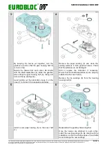
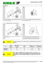
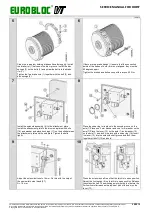
Adjust the encoder support.
The bearings of the encoder (B) can be damaged due to
continuous radial force causing overheating. Therefore the
encoder support must be adjusted so that it causes very
minimal radial load to the encoder. The support (A) must be
straight, not bent.
However, the support cannot have any clearance, so all the
support screws must be tightened carefully.
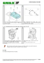
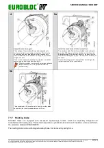
Install the encoder cable to the terminal box.
The encoder cable (D) must be a shielded round cable and
grounded 360 degrees at both ends. Ensure that the cable
shield grounding to the terminal box (E) is made so that the
claws of the cable gland (F) are in touch with the shielding of
the cable.
Connect the wiring inside the terminal box according to the
instructions given by the manufacturer.
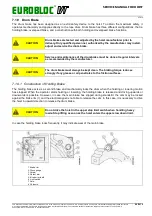
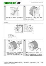
When the encoder is mounted, the maximum allowed
radial movement is 0.1 mm (measured from the
encoder body).
5b
The encoder cable (D) must be as far from the motor cables
as possible (the recommended distance is 20 cm).
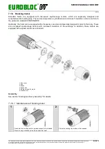
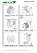
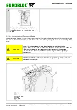
7.1.7 Hoisting brake
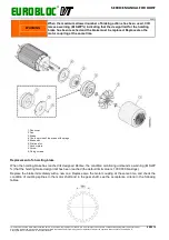
Standard hoists are equipped with two-speed squirrel-cage motors, which are especially designed and
manufactured for hoisting duty. The motors incorporate a cylindrical rotor and class F insulation, and are conform to
the protection standard IP54/DIN40050.
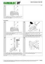
The hoisting brake is an electromagnetic safety brake that is closed by spring force.

