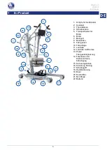
background image

Albatros II 

2022-08 


Vor der Benutzung 


EN 


NL


DE 


Vor der Benutzung 

2.1 

Bestimmungsgemäße Verwendung 

Dieser  Abschnitt  enthält  eine  kurze  Beschreibung  der  vorgesehenen  Benutzung  Ihres 
Patientenlifters.  Darüber  hinaus  enthalten  die  Anweisungen  in  den  anderen  Abschnitten 
zusätzliche  Warnhinweise.  Auf  diese  Weise  wollen  wir  Sie  auf  die  Möglichkeit  einer 
unsachgemäßen Benutzung hinweisen. 

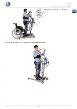
  Indikationen  und  Kontraindikationen:  Dieser  Patientenlifter  ist  für  die  Bedienung  durch  eine 

Pflegekraft vorgesehen, um sitzende Patienten  z.B. zwischen Rollstühlen, Pflegebetten und 
Badezimmern  zu  transferieren.  Der  Patientenlifter  ist  als  Transport-/Transferhilfe  für  ältere 
Personen  oder  Personen  mit  Lähmungen,  Gliedmaßenverlust  oder  -defekten,  steifen  oder 
beschädigten  Gelenken,  Herz-Kreislauf-Problemen,  Kachexie,  ...  konzipiert  und  hergestellt. 
Bei bestimmungsgemäßem Gebrauch dieses Produkts sind keine Kontraindikationen bekannt. 

  Dieser Patientenlifter ist für den Innenbereich geeignet.  

  Er ist ausschließlich dafür konzipiert und gefertigt, eine (1) Person mit einem Gewicht mit einem 

Maximalgewicht  von  150  kg.  Er  ist  nicht  dafür  vorgesehen,  Sachen  oder  Objekte  zu 
transportieren oder zu anderen Zwecken als zuvor beschrieben benutzt zu werden. 

  Verwenden Sie ausschließlich von Vermeiren genehmigte Zubehör- oder Ersatzteile.  

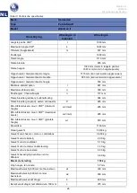
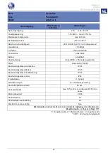
  Sehen Sie sich auch die technischen Daten und die Einschränkungen Ihres Patientenlifters in 

Abschnitt 7 an. 

  Die Garantie für dieses Produkt beruht auf dessen normaler Benutzung und Wartung wie in 

diesem Handbuch beschrieben. Schäden an Ihrem Produkt, die auf unsachgemäße Benutzung 
oder mangelnde Wartung zurückzuführen sind, führen zum Erlöschen der Garantie. 

2.2 

Allgemeine Sicherheitshinweise 

  Gefahr von Personen- und/oder Sachschäden 

Bitte  lesen  und  befolgen  Sie  die  Anweisungen  in  dieser  Bedienungsanleitung,  da  andernfalls 
Verletzungsgefahr besteht oder Ihr Patientenlifter beschädigt werden könnte. 


Beachten Sie bei der Benutzung die folgenden allgemeinen Warnhinweise: 

  Die  Nutzung  und  der  Betrieb  des  Patientenlifters  ist  nu  durch  autorisierte  Personen 

durchzuführen, die auf die Nutzung des Lifters geschult worden sind.


  Überschreiten Sie nicht die Höchstlast für den Patientenlifter. Dies führt zur Abschaltung des 

Steuergeräts. 

  Bei  unterschiedlichen  Benutzergewichten  für  Patientenlifter  und  Hebegurte  ist  immer  das 

niedrigste Benutzergewicht zu beachten. 

  Während des Hebevorgangs muss eine Begleitperson anwesend sein. 

  Benutzen Sie Ihren Rollstuhl nicht, wenn Sie unter dem Einfluss von Alkohol, Medikamenten 

oder anderen Substanzen stehen, die Ihre Fahrtüchtigkeit beeinträchtigen könnten.  

  Beachten  Sie,  dass  einige  Komponenten  Ihres  Patientenlifters  durch  Einflüsse  wie 

Umgebungstemperatur,  Sonneneinstrahlung  oder  Heizvorrichtungen  sehr  heiß  oder  kalt 
werden können.  Seien Sie daher vorsichtig beim Berühren.  

  Ihr  Patientenlifter  wurde  auf  elektromagnetische  Verträglichkeit  geprüft  und  erfüllt  die 

entsprechende Norm. Dennoch können Quellen elektromagnetischer Felder wie Mobiltelefone, 
Stromgeneratoren oder Energiequellen mit hoher Leistung die Leistung Ihres Patientenlifters 
beeinträchtigen.  Andererseits  kann  auch  die  Elektronik  Ihres  Patientenlifters  Einfluss  auf 
andere elektronische Geräte haben.  

  Benutzen Sie den Patientenlifter nur auf ebenen Flächen, so dass sich alle Laufrollen auf dem 

Boden  befinden  und  ausreichend  Kontakt  für  einen  sicheren  Betrieb  des  Patientenlifters 
haben.  Nehmen  Sie  während  des  Transfers  eines  Pflegebedürftigen  keine  Hindernisse  mit 
dem Patientenlifter. 

VORSICHT

Summary of Contents for Albatros

Page 1: ... S A T I O N G E B R U I K S A A N W I J Z I N G G E B R A U C H S A N W E I S U N G M A N U A L E D I I S T R U Z I O N I M A N U A L D E I N S T R U C C I O N E S I N S T R U K C J A O B S Ł U G I N Á V O D K O B S L U Z E Albatros II ...

Page 2: ...iding is deel van het product en dient bij iedere product te worden geleverd Versie B 2022 08 DE Hinweise für den Fachhändler Diese Gebrauchsanweisung ist Bestand teil des Produkts und ist bei jeder Produkts auszuhändigen Version B 2022 08 IT Istruzioni per il rivenditore Il presente Manuale di istruzioni è parte integrante del prodotto e deve essere fornito assieme alla prodotto Versione B 2022 0...

Page 3: ...English Français Nederlands Deutch Italiano Español Polski Czech User manual Manuel d utilisation Gebruiksaanwijzing Bedienungshandbuch Manuale di istruzioni Manual de instrucciones Instrukcja obsługi Návod k obsluze ...

Page 4: ...This page is intentionally left blank ...

Page 5: ...t 5 3 2 Slings 8 3 3 Battery and charging 11 3 4 Emergency 12 4 Installation and adjustment 13 4 1 Delivery 13 4 2 Assembly or dismantling 13 4 3 Changing the battery 20 5 Maintenance 21 5 1 Time of maintenance 21 5 2 Shipping and storage 22 5 3 Cleaning 22 5 4 Disinfection 22 5 5 Inspection 23 5 6 Expected lifespan 23 5 7 Reuse 23 5 8 End of use 23 6 Troubleshooting 24 7 Technical specifications ...

Page 6: ...g the lifetime of your product please take good care of it and have it checked and serviced on a regular basis This manual reflects the latest product developments Vermeiren has the right to implement changes to this type of product without any obligation to adapt or replace similar products previously delivered Pictures of the product are used to clarify the instructions in this manual Details of...

Page 7: ...older for motor 6 Motor 7 Leg belt 8 Leg support 9 Chassis 10 Footplate 11 Caster 12 Caster with brake 13 Chassis expansion pedal 14 Footrests with velcro fastening 15 Safety spindle 16 Foldaway lock 17 Handle for pushing 18 Manual control 19 Pole 20 Control box 21 Emergency stop 22 Battery 2 10 9 8 5 11 3 6 7 14 12 13 1 4 15 16 17 18 19 20 1 21 22 ...

Page 8: ...neral warnings in mind during use The patient hoist must only be operated by qualified staff who have been instructed or trained in its specific application Do not exceed the maximum load for the patient hoist This will shut down the control box In case of different user weights for patient hoist and slings always observe the lowest user weight An attendant needs to be present during the lifting o...

Page 9: ...h To get the lift around a wheelchair or other seating furniture or to increase the stability of the lift in the standing position the separation of the chassis legs can be increased Stand behind the assembled lift and take hold of the handles for pushing the patient hoist on the left and right next to the control box Press the lever at the bottom of the chassis left or right down with your foot a...

Page 10: ...ion and to support the legs of the patient while standing up The leg supports can be adjusted in depth and 9 different heights Height from footplate to top of leg support Position 690 mm Hole 1 665 mm Hole 2 640 mm Hole 3 Do not use Hole 4 Do not use Hole 5 495 mm Hole 6 470 mm Hole 7 445 mm Hole 8 420 mm Hole 9 3 1 5 Thorax support To stabilize and support your thorax the lift is equipped with th...

Page 11: ...he patient hoist Risk of injuries Be careful passing through restricted passages e g doors 1 Stand behind the patient hoist and grasp the handles left and right next to the control box with both hands 2 Make sure that both back caster brakes have been released 3 Push the patient hoist slowly into the desired position When it is not loaded we advise you to pull the patient hoist backwards which mak...

Page 12: ...e same place Be careful you do not touch any objects with the legs of the patient hoist 8 When you are turned in the good position you can lift the patient down 3 2 Slings Risk of injuries Only use appropriate slings for the patients Do not use damaged slings Read the full slings manual first Only use compatible slings approved by Vermeiren 3 2 1 Attachment points on patient lift CAUTION A Attachm...

Page 13: ...he thorax belt with the four straps to the patient hoist Phase II Lifting Use the manual control slowly to lift the patient up The patient must hold the handgrips during lifting Phase III Stabilization In the last step after lifting to the vertical position the patient is stabilized by thorax belts Thorax belts are mounted on both sides of the thorax support Afterwards you can remove the vest To c...

Page 14: ...Albatros II 2022 08 Using the patient hoist 10 EN NL View properly how the patient is stabilized Buttons for waist belt attachment ...

Page 15: ...should regularly recharge the batteries in order to ensure that the hoist remains usable and to extend the lifespan of the batteries The control box will give a warning sound to tell you when the battery charge is low Primary voltage 24 VDC Ambient temperature 5 C to 40 C Ambient storage temperature 10 to 50 C Relative storage humidity max 80 non condensing Conformity tested in accordance with IEC...

Page 16: ...efore recharge the batteries at least once a month even if they are not being used 3 4 Emergency In cases for emergency the emergency stop and the function for lowering in an emergency must be used 3 4 1 Emergency stop In emergencies and during assembly and disassembly the emergency stop is activated by pressing the red button on the control box Push on the button and turn in the direction of the ...

Page 17: ...ts are damaged example by transport Please note that the basic configuration may vary from one European country to another Please contact the specialist dealer in your country for more information 4 2 Assembly or dismantling 4 2 1 Unpacking L WARNING Risk of injury After unpacking and before further assembly always first confirm that the emergency stop the red pushbutton on the control box is pres...

Page 18: ... now be removed easily 2 Undo the transport lock wing screw gently and the pole can now be raised 2 a The standing position safety traction screw clicks audibly into place once the pole is put in its final position 3 L WARNING Risk of injury Make sure that the safety spindle is correctly inserted Fix the pole in place by pushing the safety spindle at the end of the pole in with the pushbutton depr...

Page 19: ...tilever arm from the top end of the pole This is possible by pulling on the pen 5 Mount the slide column with the foot support attachment in the tube of the patient hoist frame Retighten the lever 6 Attach the slide and slide holder to the cantilever arm with the locking pin ...

Page 20: ...Take care that the actuator is positioned very well between the cantilever arm 9 Attach the footplate with the hooks to the chassis of the patient hoist 10 Attach the leg support with the locking pin Position the leg support to the desired height and depth 11 Mount the thorax support to the slide column with the locking pin in a comfortable height for every patient ...

Page 21: ...d to avoid unintentional adjustment movements 1 Secure the two casters at the back of the chassis by pressing the caster brake plates down gently to their end stops with the tip of your foot To release the brake push the brake plate gently back up again with the front of your foot until the casters are free 2 Remove the thorax support from the slide column with the locking pin 3 Remove the leg sup...

Page 22: ...r arm by removing the locking pin 6 Move the actuator to the bottom position and place the actuator in the black clip 7 Remove the slide and slide holder from the cantilver arm with the locking pin 8 Loosen the lever Remove the slide column and foot support attachment out the tube of the patient hoist frame ...

Page 23: ...Once the pole is unlocked its own weight can cause considerable downward forces to be exerted Pull out the standing position safety traction screw until the pole is released and can be tilted The pole can now be tilted forwards Tip the pole as far as possible forward 12 L WARNING Risk of injury Make sure that the safety spindle is correctly inserted Fix the pole in place by pushing the safety spin...

Page 24: ...e battery at temperatures below 5 C or above 50 C the ideal is 20 C If the battery is opened all liability of the manufacturer shall be voided as well as any claim The battery of the patient hoist can be swapped by an integrated clip system To swap the battery pull on the integrated clip system The plate will be lifted and the battery can be taken off the holder control box ...

Page 25: ...evant cables no damage such as wires that have become frayed broken or exposed Check that the electrical adjustment of the cantilever arm is working properly using the manual control Battery status charge the battery when necessary see 3 3 Approx every 8 weeks Depending on the frequency of use check the following Lubrication of the joints of the cantilever arm Condition of the casters Whether ther...

Page 26: ...ent hoist consists of steel components The high quality of the surface layer guarantees optimal protection against corrosion If the outer coat is damaged by scratching or in some other way get your specialist dealer to repair the affected surface When cleaning only use warm water and normal household detergents and soft brushes and cloths Ensure that no wetness gets into the tubes 5 3 3 Electronic...

Page 27: ...ist drives during a test drive noises speed free running etc if necessary Measure the performance first with no load and then with the nominal load SWL to investigate the wear and tear of the motors by comparing the values for the electric current against the values when it was delivered Functional test of the emergency stop Functional test of the emergency lowering Completeness of the delivery co...

Page 28: ...the actuator 2 Use a patient hoist with higher maximum user weight 3 Check connections If necessary connect manual control or actuator 4 Check battery is installed or the connection of the battery 5 Charge the batteries or replace 6 Deactivate the emergency stop Lowering the patient in case of emergency does not work There is required a minimum weight load to lower the patient If the patient weigh...

Page 29: ...Albatros II 2022 08 Technical specifications 25 EN NL 7 Technical specifications Forward direction ...

Page 30: ... 769 mm Leg height Frame height n 117 mm Overall width closed external dimension 584 mm Overall width opened castors forwards P 945 mm Min distance between wall CSP minimum height w3 w2 285 mm Min distance between wall CSP maximum reach w2 w3 285 mm Min distance between wall CSP maximum height w1 870 mm Turning circle 1160 mm Total weight 50 60 kg Weight of chassis motor control box 34 50 kg Weigh...

Page 31: ...B5X 5N force required to operate Motor Linak LA34 7500N Control box protection class IPX4 Battery protection class IPX5 Manual control protection class IPX5 Motor protection class IP54 Insulation class II Type B Operational performance approx 40 lifts per charge Lifting Lowering speed 28 sec Periodic operation max 10 or 2 min continuous operation 18 min pauses Battery capacity 2 9 Ah Emergency sto...

Page 32: ......

Page 33: ... Utilisation du lève personne 6 3 2 Sangles 9 3 3 Batterie et charge 12 3 4 Urgence 13 4 Montage et réglage 14 4 1 Livraison 14 4 2 Montage ou démontage 14 4 3 Remplacement de la batterie 21 5 Maintenance 22 5 1 L entretien 22 5 2 Expédition et stockage 22 5 3 Nettoyage 23 5 4 Désinfection 23 5 5 Inspection 24 5 6 Durée de vie attendue 24 5 7 Réutilisation 24 5 8 Mise au rebut 24 6 Résolution des ...

Page 34: ...curité et prolonger la durée de vie de votre produit prenez en grand soin et faites le contrôler et entretenir régulièrement Ce manuel est le reflet des derniers développements du produit Vermeiren a le droit d apporter des modifications à ce type de produit sans être tenu d adapter ou de remplacer des produits similaires fournis précédemment Les images sont fournies afin de clarifier les instruct...

Page 35: ...rax 4 Colonne de guidage 5 Support de transport pour le moteur 6 Moteur 7 Ceinture pour les jambes 8 Repose jambe 9 Châssis 10 Palette 11 Roulette directrice 12 Roue avec frein 13 Pédale d écartement du châssis 14 Repose pied avec une fixation en velcro 15 Axe de fixation 16 Verrouillage escamotable 17 Barres du poussoir 18 Commande manuelle 19 Mât 20 Boîte de contrôle 21 Arrêt d urgence 22 Batter...

Page 36: ...résent manuel d utilisation Autrement vous pourriez vous blesser ou votre lève personne pourrait être endommagé Tenez compte des avertissements généraux suivants pendant l emploi Seules des personnes autorisées formées à l utilisation et au fonctionnement du lève personne peuvent le manipuler Ne dépassez pas la charge maximale du lève personne Le boîtier de commande s arrêtera alors En cas de poid...

Page 37: ...prudent avec le feu en particulier avec les cigarettes incandescentes en effet les sangles risquent de s enflammer En cas d incident grave impliquant votre produit informez Vermeiren ou votre revendeur spécialisé ainsi que l autorité compétente de votre pays ...

Page 38: ...est possible d augmenter l écartement du châssis pour entourer un fauteuil roulant ou un autre siège avec le lève personne mais aussi pour améliorer la stabilité du lève personne En vous tenant derrière le lève personne une fois celui ci monté et saisissez les poignées de poussée du lève personne à gauche et à droite à côté du boîtier de commande Appuyez avec le pied légèrement vers le bas sur la ...

Page 39: ...ale Le repose jambes peut être réglé en profondeur ainsi que selon 9 hauteurs différentes Distance entre la plaque repose pieds et le sommet du repose jambes Position 690 mm Trou 1 665 mm Trou 2 640 mm Trou 3 Ne pas utiliser Trou 4 Ne pas utiliser Trou 5 495 mm Trou 6 470 mm Trou 7 445 mm Trou 8 420 mm Trou 9 3 1 5 Support pour le thorax Afin de stabiliser et de soutenir votre thorax le lève perso...

Page 40: ...é N utilisez la fonction de levage qu au centre de la plage de réglage 3 1 7 Déplacement du lève personne Risques de blessures Soyez prudent lorsque vous franchissez des passages étroits portes par exemple 1 Placez vous derrière le lève personne en tenant à deux mains les poignées gauche et droite à côté du boîtier de commande 2 Vérifiez que les deux freins des roues arrière soient desserrés 3 Pou...

Page 41: ... boîtier de commande 7 Maintenant tournez le lève personne prudemment doucement sur son axe Faites attention à ne toucher aucun objet avec les pieds du lève personne 8 Quand vous êtes arrivés dans la bonne position vous pouvez descendre le patient 3 2 Sangles Risques de blessures Veillez à utiliser les sangles adaptée au patient N utilisez pas de sangles endommagée Lisez d abord le manuel complet ...

Page 42: ...les de fixation Phase II Soulever Utilisez prudemment la commande manuelle pour soulever le patient Demandez au patient de saisir les poignées pendant le soulèvement Phase III Stabilisation Au cours de la dernière étape après le soulèvement en position verticale le patient est stabilisé grâce aux ceintures pour le thorax Les ceintures pour le thorax sont montées des deux côtés du support pour le t...

Page 43: ...Albatros II 2022 08 Utilisation du lève personne 11 EN FR NL Regardez de quelle manière le patient est stabilisé Boutons pour fixer la ceinture à la taille ...

Page 44: ...èrement les batteries afin de maintenir le lève personne en état de fonctionnement et de bénéficier de la durée de vie optimale des batteries Le boîtier de commande émet un signal sonore dès que la charge de la batterie est faible Tension primaire 24 V CC Température environnante 5 C à 40 C Température environnante pour le stockage 10 à 50 C Humidité relative pour le stockage Max 90 sans condensat...

Page 45: ...c à recharger les batteries au moins une fois par mois même si vous ne devez pas vous en servir 3 4 Urgence En cas d urgence utilisez le bouton d urgence ainsi que la fonction d abaissement d urgence 3 4 1 Arrêt d urgence En cas d urgence ainsi que lors du montage et du démontage vous pouvez activer l arrêt d urgence en actionnant le bouton rouge du boîtier de commande Appuyez sur le bouton et tou...

Page 46: ... de tous ces éléments et qu aucun n a été endommagé en particulier durant le transport Veuillez noter que la configuration de base pour l Europe peut varier d un pays à l autre Votre revendeur spécialisé local pourra vous fournir toutes précisions utiles 4 2 Montage ou démontage 4 2 1 Deballage L AVERTISSEMENT Risque de blessures Une fois l équipement déballé et avant de procéder à son assemblage ...

Page 47: ...l axe de fixation 2 Libérez délicatement la sécurité de transport vis à croisillon pour pouvoir orienter le mât 2 a La sécurité vis de traction s enclenche de manière audible lorsque le mât est placé dans sa position finale 3 L AVERTISSEMENT Risque de blessure Veillez à ce que l axe de fixation soit bien en place Fixez le mât en insérant l axe de fixation en bas du mât en appuyant sur le bouton su...

Page 48: ...ure du mât Vous le faites en tirant prudemment sur la broche 5 Montez la colonne de direction avec la fixation du repose pieds dans la conduite du châssis du lève personne Fixez à nouveau le levier 6 Fixez le conducteur et le support de conduction au bras de levage avec les goupilles d arrêt ...

Page 49: ... le moteur est bien placé entre le bras de levage 9 Fixez la palette avec les crochets sur le châssis du léve personne 10 Fixez le repose jambe à l aide de la goupille d arrêt Placez le repose jambe à la hauteur et dans la profondeur souhaitées 11 Montez le support pour le thorax sur la colonne de direction avec la goupille d arrêt dans une hauteur confortable pour chaque patient ...

Page 50: ...out réglage intempestif 1 Bloquez les deux roues à l arrière du châssis en appuyant légèrement de la pointe du pied sur la patte du frein des roues en l abaissement jusqu à ce qu elles soient bloquées Pour desserrer les freins soulever de la pointe du pied sur la pédale de frein vers le haut jusqu à ce que les roues soient libérées 2 Enlevez le support pour le thorax de la colonne de direction ave...

Page 51: ... arrêt 6 Déplacez le moteur de la position inférieure et fixez le moteur dans la pince noire 7 Enlevez le conducteur et le support de conduction du bras de levage avec la goupille d arrêt 8 Détachez le levier Enlevez la colonne de direction et la fixation du repose jambe dans la conduite du châssis du lève personne ...

Page 52: ...éverrouillé des forces descendantes considérables peuvent faire leur apparition en raison de son propre poids Tirez la sécurité vis de traction jusqu à ce que le mât puisse être incliné Vous pouvez alors incliner le mât vers l avant Faites basculer le mât le plus loin possible vers l avant 12 L AVERTISSEMENT risque de lésion Veillez à ce que l axe de fixation soit bien en place Fixez le mât en ins...

Page 53: ...s températures inférieures à 5 C ou supérieures à 50 C la température idéale étant de 20 C Le constructeur décline toute responsabilité et réclamation en cas d ouverture de la batterie Le remplacement de batterie du lève personne s effectue au moyen d un dispositif de clip intégré Pour remplacer la batterie tirez sur ce dispositif afin de soulever la plaque et de retirer la batterie de son logemen...

Page 54: ...e réglage électrique du bras en porte à faux fonctionne correctement à l aide de la commande manuelle État de la batterie chargez la batterie si nécessaire cf 3 3 Environ toutes les 8 semaines En fonction de la fréquence d utilisation contrôlez les éléments suivants Lubrification des articulations de la potence État des roues Des dommages sont ils visibles sur le boîtier de commande batterie charg...

Page 55: ...omposé d éléments en acier La grande qualité de la couche de surface garantit une protection optimale contre la corrosion Si la couche externe est endommagée par une rayure ou autre faites réparer la surface concernée par votre distributeur Pour le nettoyage utilisez exclusivement de l eau chaude et des détergents domestiques normaux avec des brosses ou tissus doux Veillez à ne pas faire entrer d ...

Page 56: ...s de levage en effectuant des tests de vérification du bruit de la vitesse de la course etc ainsi que si nécessaire mesurez les performances d abord sans charge puis avec la charge nominale SWL afin de détecter tout signe d usure du moteur en comparant les valeurs de courant électrique obtenues avec les valeurs de référence lors de la livraison Contrôle de fonctionnement de l arrêt d urgence Contr...

Page 57: ...sez un lève personne adapté au poids du patient 3 Vérifiez les connexions Connectez si nécessaire la commande manuelle ou l actionneur 4 Vérifiez que la batterie soit installée et connectée 5 Rechargez ou remplacez la batterie 6 Désactivez le bouton d arrêt d urgence Le dispositif d abaissement manuel en cas d urgence ne fonctionne pas L abaissement d urgence n est possible qu en présence d un poi...

Page 58: ...Albatros II 2022 08 Spécifications techniques 26 EN FR NL 7 Spécifications techniques Avant direction ...

Page 59: ...mal du bras q 769 mm Hauteur du bras hauteur de châssis n 117 mm Largeur totale fermé cote extérieure 584 mm Largeur totale ouvert roues en avant P 945 mm Distance minimale entre paroi et PAC hauteur minimale w3 w2 285 mm Distance minimale entre paroi et PAC portée maximale w2 w3 285 mm Distance minimale entre paroi et PAC hauteur maximale w1 870 mm Rayon de braquage 1160 mm Masse totale 50 60 kg ...

Page 60: ...ande manuelle Linak HB5X force d actionnement 5N Moteur Linak LA34 7500N Classe de protection du boîtier de commande IPX4 Classe de protection de la batterie IPX5 Classe de protection de la commande manuelle IPX5 Classe de protection du moteur IP54 Classe d isolation II Type B Rendement env 40 levages par chargement Vitesse de levage abaissement 28 sec Utilisation périodique Max 10 ou 2 minutes d ...

Page 61: ...ft 5 3 2 Tilbanden 8 3 3 Batterij en laden 11 3 4 Noodgeval 12 4 Montage en afstelling 13 4 1 Levering 13 4 2 Montage of demontage 13 4 3 De batterij verwisselen 20 5 Onderhoud 21 5 1 Tijdstippen voor onderhoud 21 5 2 Verpakking en opslag 21 5 3 Schoonmaak 22 5 4 Desinfecteren 22 5 5 Inspectie 23 5 6 Verwachte levensduur 23 5 7 Hergebruik 23 5 8 Beëindiging van gebruik 23 6 Probleemoplossing 24 7 ...

Page 62: ...te verlengen raden we u aan om er goed zorg voor te dragen en om regelmatig nazicht en onderhoud te laten uitvoeren Deze handleiding houdt rekening met de recentste productontwikkelingen De Firma Vermeiren behoudt zich het recht voor om wijzigingen aan dit type product door te voeren zonder verplicht te zijn om voordien geleverde producten aan te passen of te vervangen Afbeeldingen van het product...

Page 63: ... 6 Motor 7 Riem voor de benen 8 Beensteun 9 Chassis 10 Voetplaat 11 Zwenkwiel 12 Zwenkwiel met rem 13 Pedaal voor spreiding chassis 14 Voetsteun met bevestiging in velcro 15 Vergrendelas 16 Opklapbare vergrendeling 17 Duwbeugels 18 Handbediening 19 Mast 20 Controlebox 21 Noodstopknop 22 batterij 2 10 9 8 5 11 3 6 7 14 12 13 1 4 15 16 17 18 19 20 1 21 22 ...

Page 64: ...iging aan uw patiëntenlift Houd rekening met de volgende algemene waarschuwingen tijdens het gebruik De patiëntenlift mag alleen worden gebruikt en bediend door geautoriseerde personen die zijn opgeleid voor het gebruik van de lift Overschrijd de maximaal toegestane belasting van de patiëntenlift niet hierdoor wordt de besturingskast uitgeschakeld Indien de patiëntenlift en tilbanden verschillende...

Page 65: ...ding onderstel Om met de lift een rolstoel of andere zitmogelijkheden te omsluiten maar ook om de stabiliteit van de lift te verhogen kunt u de afstand tussen de onderstelpoten vergroten Ga achter de gemonteerde lift staan en houd de duwbeugels van de patiëntenlift vast aan de linker en rechterkant naast de controlebox Druk met een voet het pedaal van het onderstel links of rechts zachtjes naar be...

Page 66: ...nt tijdens het staan te ondersteunen De beensteunen kunnen in diepte en in 9 verschillende hoogten worden afgesteld 3 1 5 Thorax ondersteuning Om uw thorax te stabiliseren en te ondersteunen is de lift voorzien van een thorax kussen en velcro riemen om te stabiliseren VOORZICHTIG Hoogte van de voetplaat tot de top van de beensteun Positie 690 mm Boring 1 665 mm Boring 2 640 mm Boring 3 Niet gebrui...

Page 67: ...doorgangen gaat bijv deuren 1 Ga achter de patiëntenlift staan en grijp de duwbeugels links en rechts naast de controle box met beide handen vast 2 Controleer of beide remmen van de achterste wielen los zijn 3 Schuif de patiëntenlift langzaam in de gewenste stand In onbelaste toestand kunt u de patiëntenlift het beste achterwaarts rijden zodat hindernissen bijvoorbeeld deurkozijnen kamerhoeken of ...

Page 68: ...t de benen van de patiëntenlift 8 Wanneer u in de goede positie bent rondgedraaid kan u de patiënt terug neerlaten 3 2 Tilbanden Gevaar voor letsel Gebruik alleen geschikte tilbanden voor de patiënten Gebruik geen beschadigde tilbanden Lees eerst de volledige handleiding van de tilbanden Gebruik enkel tilbanden die door Vermeiren zijn goedgekeurd 3 2 1 Bevestigingspunten op patiëntenlift VOORZICHT...

Page 69: ... behulp van de vier bevestigingsriemen Fase II Tillen Gebruik voorzichtig de handbediening om de patiënt naar boven te tillen Laat de patiënt de handgrepen vastnemen tijdens het tillen Fase III Stabilisatie In de laatste stap na het tillen in de verticale positie is de patiënt gestabiliseerd door de thorax gordels De Thorax gordels zijn langs beide kanten van de steun voor de thorax gemonteerd Een...

Page 70: ...Albatros II 2022 08 De patiëntenlift gebruiken 10 NL Kijk goed hoe de patiënt is gestabiliseerd Knoppen om de taillegordel te bevestigen ...

Page 71: ...terijen regelmatig opnieuw op te laden om ervoor te zorgen dat de lift bruikbaar blijft en om de levensduur van de batterijen te verlengen De controlebox geeft een waarschuwingssignaal om u te laten weten dat de batterij bijna leeg is Primaire spanning 24 V DC Omgevingstemperatuur 5 C tot 40 C Omgevingstemperatuur bij opslag 10 tot 50 C Relatieve luchtvochtigheid bij opslag max 80 niet condenseren...

Page 72: ...noodgevallen moeten de noodstopknop en de functie voor het omlaag brengen van de patiënt worden gebruikt 3 4 1 Noodstopknop In noodgevallen en tijdens montage en demontage wordt de noodrem geactiveerd door op de rode knop op de controle box te drukken Druk op de knop en draai in de richting van de pijlen Als de knop volledig naar achteren is gedrukt draai dan terug in de tegenovergestelde richting...

Page 73: ...everd en er geen producten zijn beschadigd tijdens het transport bijvoorbeeld Denk eraan dat de basis configuratie kan variëren in de verschillende Europese landen Neem voor meer informatie contact op met de vakhandelaar in uw land 4 2 Montage of demontage 4 2 1 Uitpakken L WAARSCHUWING Risico op letsel Na het uitpakken voordat u verder monteert controleert u altijd eerst of de noodstopknop de rod...

Page 74: ...den uitgetrokken 2 Maak de transportbeveiliging knevelschroef enigszins los en de mast kan nu rechtop worden gezet 2 a De standvergrendeling trekschroef klikt hoorbaar als de mast in zijn eindpositie wordt opgesteld 3 L WAARSCHUWING Kans op letsel Let erop dat de vergrendelas op de juiste wijze is geplaatst Vergrendel de mast door de vergrendelas aan het einde van de mast met ingedrukte drukknop z...

Page 75: ...venkant van de mast U doet dit door voorzichtig aan de pin te trekken 5 Monteer de geleidingskolom met de bevestiging van de voetsteun in de buis van het frame van de patiëntenlift Zet de hendel terug vast 6 Bevestig de geleider en geleidingshouder aan de hefarm met de pijpborgpen ...

Page 76: ...g ervoor dat de motor goed tussen de hefarm wordt geplaatst 9 Bevestig de voetplaat met de haken op het chassis van de patiëntenlift 10 Bevestig de beensteun met behulp van de pijpborgpen Plaats de beensteun op de gewenste hoogte en diepte 11 Monteer de thorax ondersteuning aan de geleidingskolom met de pijpborgpen in een comfortabele hoogte voor elke patiënt ...

Page 77: ...bedoelde bewegingen tijdens het afstellen te voorkomen 1 Vergrendel de twee wielen aan de achterzijde van het onderstel door met de voet de rempedaal van de wielen zachtjes omlaag te drukken tot de wielen blokkeren Om de rem los te maken drukt u met de voet de rempedaal weer zachtjes naar boven totdat de wielen worden vrijgegeven 2 Verwijder de thorax ondersteuning van de geleidingskolom met de pi...

Page 78: ...wijderen 6 Verplaats de motor naar de onderste positie en bevestig de motor in de zwarte klem 7 Verwijder de geleider en geleidingshouder van de hefarm met behulp van de pijpborgpen 8 Maak de hendel los Verwijder de geleidingskolom en bevestiging voor de beenteun uit de buis van het frame van de patiëntenlift ...

Page 79: ...endeld kan door zijn eigen gewicht aanzienlijke neerwaartse krachten ontstaan Trek aan de standvergrendeling trekschoef totdat de mast voor kantelen wordt vrijgegeven De mast kan nu naar voren worden gekanteld Kantel de mast zo ver mogelijk naar voren 12 L WAARSCHUWING Kans op letsel Let erop dat de vergrendelas op de juiste wijze is geplaatst Vergrendel de mast door de vergrendelas aan het einde ...

Page 80: ...bij temperaturen onder 5 C of boven 50 C de ideale temperatuur is 20 C Zowel de aansprakelijkheid van de fabrikant als welke claim dan ook vervalt als de batterijen worden geopend De batterij van de patiëntenlift kan worden verwisseld via een ingebouwd klemsysteem Als u de batterij wilt verwisselen drukt u op het ingebouwde klemsysteem De plaat komt omhoog en de batterij kan uit de houder worden g...

Page 81: ...ening Batterijstatus laad de batterij op indien nodig zie 3 3 Ongeveer om de 8 weken Afhankelijk van de regelmaat waarmee u het product gebruikt dient u de volgende punten te controleren Smering van de scharnierverbindingen van de hefarm Toestand van de wielen Is er zichtbare schade aan de behuizing van de besturingskast batterij batterijlader indien beschikbaar en de handbediening Toestand van de...

Page 82: ...behandeling is een optimale corrosiebescherming gegarandeerd Wanneer de buitenste coating door krassen e d is beschadigd laat u deze door uw vakhandelaar repareren Voor het schoonmaken gebruikt u alleen warm water en algemeen verkrijgbare huishoudelijke reinigingsmiddelen evenals zachte borstels en doeken Let op dat er geen vocht in de buizen komt 5 3 3 Elektronicabehuizing L WAARSCHUWING Kans op ...

Page 83: ...stelbaarheidsbereik vervorming slijtage Controleer de werking van de motoraandrijvingen tijdens een testrit geluid snelheid soepelheid etc Indien nodig meten van het vermogen eerst zonder last daarna met de nominale last SWL om zo eventuele slijtage van de motoren te kunnen onderzoeken door de waarden van de elektrische stroom te vergelijken met de waarden bij levering Functionele test van de nood...

Page 84: ...ijving 2 Gebruik een patiëntenlift met een hoger maximaal gebruikersgewicht 3 Controleer de aansluitingen Sluit indien nodig de handbediening of aandrijving aan 4 Controleer of de batterij of de aansluiting van de batterij is geplaatst 5 Laad de batterijen op of verwissel ze 6 Schakel de noodstopknop uit Het omlaag brengen van de patiënt in een noodgeval werkt niet Er is een vereist minimaal gewic...

Page 85: ...Albatros II 2022 08 Technische specificaties 25 NL 7 Technische specificaties Voorwaartse richting ...

Page 86: ...n q 769 mm Poothoogte Chassishoogte n 117 mm Totale breedte gesloten buitenafmeting 584 mm Totale breedte geopend wielen voorwaarts P 945 mm Min Afstand tussen muur COP minimum hoogte w3 w2 285 mm Min Afstand tussen muur COP maximaal bereik w2 w3 285 mm Min Afstand tussen muur COP grootste hoogte w1 870 mm Draaicirkel 1160 mm Totaal gewicht 50 60 kg Gewicht van chassis motor controlebox 34 50 kg G...

Page 87: ...ening Linak HB5X 5N bedieningskracht Motor Linak LA34 7500N Beschermingsklasse controlebox IPX4 Beschermingsklasse Batterij IPX5 Beschermingsklasse handbediening IPX5 Beschermingsklasse motor IP54 Isolatieklasse II Type B Arbeidsvermogen ca 40 tilacties per lading Snelheid optillen neerlaten 28 sec Periodiek bedrijf max 10 of 2 min continu bedrijf 18 min pauze Batterijcapaciteit 2 9 Ah Noodstopkno...

Page 88: ......

Page 89: ...ters 6 3 2 Sitzsystem 9 3 3 Batterie und Aufladen 12 3 4 Notfall 13 4 Zusammenbau und Einstellung 14 4 1 Lieferumfang 14 4 2 Montage und Demontage 14 4 3 Austauschen der Batterie 21 5 Wartung 22 5 1 Wartungstermine 22 5 2 Verpackung und Lagerung 22 5 3 Reinigung 23 5 4 Desinfektion 23 5 5 Inspektion 24 5 6 Voraussichtliche Nutzungsdauer 24 5 7 Wiederbenutzung 24 5 8 Nutzungsende 24 6 Störungsbesei...

Page 90: ...auer Ihres Produkts zu verlängern sollten Sie es gut behandeln und regelmäßig überprüfen und oder warten lassen Dieses Handbuch enthält die neuesten Produktentwicklungen Vermeiren behält sich das Recht vor Veränderungen an dieser Art von Produkt vorzunehmen ohne eine Verpflichtung einzugehen ähnliche bereits ausgelieferte Produkte anzupassen oder auszutauschen Abbildungen des Produkts dienen zur V...

Page 91: ...6 Motor 7 Beingurt 8 Beinstütze 9 Fahrgestell 10 Fußauflage 11 Laufrolle 12 Laufrolle mit Bremse 13 Pedal Fahrgestellspreizung 14 Fußstützen mit Klettverschluss befestigung 15 Sicherungsachse 16 Sicherung Faltung 17 Schiebegriff 18 Handbedienung 19 Mast 20 Kontrollbox 21 Not Stopp 22 Batterie 2 10 9 8 5 11 3 6 7 14 12 13 1 4 15 16 17 18 19 20 1 21 22 ...

Page 92: ...er Garantie 2 2 Allgemeine Sicherheitshinweise Gefahr von Personen und oder Sachschäden Bitte lesen und befolgen Sie die Anweisungen in dieser Bedienungsanleitung da andernfalls Verletzungsgefahr besteht oder Ihr Patientenlifter beschädigt werden könnte Beachten Sie bei der Benutzung die folgenden allgemeinen Warnhinweise Die Nutzung und der Betrieb des Patientenlifters ist nu durch autorisierte P...

Page 93: ...r verändert noch ersetzt werden Achten Sie während des Betriebs darauf dass Finger Kleidung Gürtel Schnallen oder Schmuck nicht von den Rädern oder anderen beweglichen Teilen erfasst werden Vorsicht beim Umgang mit Feuer insbesondere brennenden Zigaretten die Sitzsysteme könnten sich entzünden Sollte sich ein schwerwiegender Zwischenfall mit Ihrem Produkt ereignet haben benachrichtigen Sie Vermeir...

Page 94: ...ult worden sind 3 1 1 Spreizung Fahrgestell Um mit dem Lifter einen Rollstuhl oder andere Sitzmöglichkeiten zu umschließen aber auch um die Standsicherheit des Lifters zu erhöhen lässt sich der Abstand der Fahrgestellschenkel vergrößern Stellen Sie sich hinter den aufgebauten Lifter und ergreifen Sie die Schiebegriffe des Patientenlifters links und rechts neben der Kontrollbox Drücken Sie mit eine...

Page 95: ...n beim Aufstehen abstützen Die Beinstützen können in der Tiefe geändert und neun verschiedene Höheneinstellungen vorgenommen werden Höhe von der Fußplatte zur Oberseite der Beinstütze Position 690 mm Bohrung 1 665 mm Bohrung 2 640 mm Bohrung 3 Nicht verwenden Bohrung 4 Nicht verwenden Bohrung 5 495 mm Bohrung 6 470 mm Bohrung 7 445 mm Bohrung 8 420 mm Bohrung 9 3 1 5 Thoraxstütze Zur Stabilisierun...

Page 96: ... nur im mittlerem Vertsellbereich 3 1 7 Bewegen des Patientenlifters Verletzungsgefahr Seien Sie in engen Durchgängen vorsichtig z B Türen 1 Stellen Sie sich hinter den Patientenlifter und ergreifen Sie die Griffe links und rechts neben der Kontrollbox mit beiden Händen 2 Stellen Sie sicher dass beide Bremsen der hinteren Laufrollen gelöst sind 3 Schieben Sie den Patientenlifter langsam in die gew...

Page 97: ...7 Nun drehen Sie den Patientenlift vorsichtig und langsam auf der Stelle Achten Sie darauf dass Sie mit den Farhbeinen gegen keine Gegenstände Stoßen 8 Haben Sie die gewünschte Position erreicht können Sie den Patienten im Lift herablassen 3 2 Sitzsystem Verletzungsgefahr Verwenden Sie nur für den Patienten geeignete Sitzsysteme Verwenden Sie keine beschädigten Sitzsystem Lesen Sie zuerst das voll...

Page 98: ...n Thoraxgurt mit den vier Gurtbändern am Patientenlift Phase II Heben Heben Sie den Patienten ganz langsam mithilfe der Handbedienung hoch Der Patient muss sich während des Hebevorgangs an den Handgriffen festhalten Phase III Stabilisierung Nach dem Hochheben in die vertikale Position wird der Patient in einem letzten Schritt mit den Thoraxgurten stabilisiert Die Thoraxgurte sind beidseits an der ...

Page 99: ...Albatros II 2022 08 Benutzung des Patientenlifters 11 EN NL DE Sehen Sie sich genau an wie der Patient stabilisiert wurde Knöpfe zum Anbringen des Hüftgurts ...

Page 100: ... Ihnen die eingebauten Batterien der Kontrollbox regelmäßig zu beladen um die Einsatzfähigkeit des Lifters zu gewährleisten und die Lebensdauer der Batterien lange aufrecht zu halten Die Kontrollbox weist mit einem Warnton darauf hin dass der Ladezustand der Batterie niedrig ist Primäre Spannung 24 V DC Umgebungstemperatur 5 C bis 40 C Umgebungstemperatur Lagerung 10 C bis 50 C Relative Luftfeucht...

Page 101: ...ie auch bei Nichtbenutzung der Batterien diese mindestens einmal im Monat auf 3 4 Notfall In Notfallsituationen muss der Notstopp und die Notabsenkungsfunktion verwendet werden 3 4 1 Not stopp Bei Notfällen und während der Montage und Demontage muss der Notstopp durch Drücken des roten Knopf an der Kontrollbox aktiviert werden Drücken Sie auf den Knopf und drehen Sie ihn in Richtung der Pfeile Wen...

Page 102: ...Sie vor der Verwendung ob alle aufgeführten Artikel in der Lieferung enthalten und nicht beschädigt sind beispielsweise durch den Transport 4 2 Montage und Demontage 4 2 1 Auspacken L WARNUNG Verletzungsgefahr Kontrollieren Sie vor dem Auspacken und der Montage immer zuerst dass der Not stopp roter Druckknopf an der Kontrollbox eingedrückt ist Die Verpackung der Patientenlifter wurde daraufhin gew...

Page 103: ...cht herausziehen 2 Lösen Sie die Transportsicherung Knebelschraube leicht und der Mast kann nun aufgerichtet werden 2 a Die Standsicherung Zug schraube rastet hörbar ein wenn der Mast in seiner Endposition aufgestellt wurde 3 L WARNUNG Verletzungsgefahr Achten Sie darauf dass die Sicherungsachse korrekt eingesteckt ist Sichern Sie den Mast indem Sie die Sicherungsachse am Ende des Mastes mit einge...

Page 104: ...er vom oberen Ende der Stange Dazu ziehen Sie an dem Stift 5 Bringen Sie die Schiebesäule mit der Fußstützen befestigung am Rohr des Patientenlifter rahmens an Ziehen Sie den Hebel wieder fest 6 Bringen Sie den Schlitten und die Schiebehalterung am Auslegerarm mit dem Sicherungsstift an ...

Page 105: ... darauf dass der Verstellmotor optimal zwischen dem Ausleger positioniert ist 9 Befestigen Sie die Fußauflage mit den Haken am Fahrgestell des Patientenlifters 10 Befestigen Sie die Beinstütze mit dem Sicherungsstift Positionieren Sie die Beinstütze in der gewünschten Höhe und Tiefe 11 Befestigen Sie die Thoraxstütze mit dem Sicherungsstift an der Schiebesäule in einer für den Patienten komfortabl...

Page 106: ...bsichtigte Verstellbewegungen zu vermeiden 1 Sichern Sie die zwei Laufrollen am hinteren Ende des Fahrgestells indem Sie mit der Fußspitze leicht die Bremspedale der Laufrollen nach unten drücken bis diese arretieren Um die Bremse zu lösen drücken Sie mit der Fußspitze die Bremspedale wieder leicht nach oben bis die Laufrollen freigegeben werden 2 Entfernen Sie die Thoraxstütze mithilfe des Sicher...

Page 107: ...gsstift entfernen 6 Bewegen Sie den Verstellmotor in die untere Position und platzieren Sie den Verstellmotor im schwarzen Clip 7 Entfernen Sie den Schlitten und den Schiebehalter vom Ausleger mit dem Sicherungsstift 8 Lösen Sie den Hebel Ziehen Sie die Schiebesäule und die Fußstützenbefestigung aus dem Vierkantrohr des Lifterrahmens ...

Page 108: ...st können aufgrund des Eigengewichtes des Mastes starke Fallkräfte auftreten Ziehen Sie die Standsicherung Zugschraube bis der Mast für das Abkippen freigegeben wird Der Mast lässt sich nun nach vorne abkippen Kippen Sie den Mast so weit wie möglich nach vorne 12 L WARNUNG Verletzungsgefahr Achten Sie darauf dass die Sicherungsachse korrekt eingesteckt ist Sichern Sie den Mast indem Sie die Sicher...

Page 109: ...uren unter 5 C oder über 50 C ideal 20 C Wird die Batterie geöffnet entfallen jegliche Haftung des Herstellers und der Gewährleistungsanspruch Die Batterie für Patientenlifter kann mithilfe eines integrierten Clipsystems ausgetauscht werden Ziehen Sie zum Austauschen der Batterie am integrierten Clipsystem Dadurch wird die Abdeckung angehoben und die Batterie kann aus der Halterung Kontrollbox ent...

Page 110: ...ektrische Verstellung des Kragarms über die Handbedienung einwandfrei funktioniert Akkustatus laden Sie den Akku ggf auf siehe Abschnitt 3 3 Ca Alle 8 wochen Abhängig von der Gebrauchshäufigkeit überprüfen folgendes Fettung der Gelenkverbindungen am Ausleger Zustand der Laufrollen Sind Gehäuseschäden an der Kontrollbox Batterie Ladegerät sofern vorhanden und der Handbedienung sichtbar Zustand der ...

Page 111: ...esteht aus Stahlkomponenten Durch die hochwertige Lackierung wird ein optimaler Korrosionsschutz gewährleistet Falls die Lackierung durch Kratzer oder ähnliches beschädigt wird sollten Sie einen Fachhändler aufsuchen um die betroffene Oberfläche instand setzen zu lassen Verwenden Sie zur Reinigung der Lackierung nur warmes Wasser und handelsübliche Haushaltsreiniger mit einer weichen Bürste und ei...

Page 112: ...iner Testfahrt Geräusche Geschwindigkeit Leichtlauf usw Falls erforderlich Messen der Leistungsaufnahme zuerst ohne Last dann mit der Nennlast SWL um evtl Verschleiß der Motoren über die Stromaufnahme ermitteln zu können und Vergleich mit den Werten bei Auslieferung Funktionsprüfung von Notstopp Funktionsprüfung von Notabsenkung Vollständigkeit des Auslieferungszustands Gebrauchsanweisung vorhande...

Page 113: ...enden Sie einen Patientenlifter mit einem höheren maximal zulässigen Patientengewicht 3 Überprüfen Sie die Anschlüsse Schließen Sie gegebenenfalls die Handbedienung bzw den Verstellmotor an 4 Prüfen Sie ob die Batterie eingesetzt ist bzw ob die Batterie angeschlossen ist 5 Laden Sie die Batterien auf bzw tauschen Sie sie aus 6 Deaktivieren Sie den Notstopp Das Absenken des Patienten in Notfallsitu...

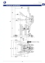
Page 114: ...Albatros II 2022 08 Technische Daten 26 EN NL DE 7 Technische Daten Vorwärtsrichtung ...

Page 115: ...69 mm Schenkelhöhe Höhe des Fahrgestells n 117 mm Gesamtbreite geschlossen Außenmaß 584 mm Gesamtbreite geöffnet Laufrollen vorne P 945 mm Min Abstand Wand ZAP geringste Höhe w3 w2 285 mm Min Abstand Wand ZAP Höchstreichweite w2 w3 285 mm Min Abstand Wand ZAP größte Höhe w1 870 mm Wendekreis 1160 mm Gesamtgewicht 50 60 kg Gewicht von Fahrgestell Motor und Kontrollbox 34 50 kg Gewicht der Batterie ...

Page 116: ...rie Linak BAJ1 Handsteuerung Linak HB5X 5N Betätigungskraft Motor Linak LA34 7500N Schutzklasse Kontrollbox IPX4 Schutzart Batterie IPX5 Schutzart Handsteuerung IPX5 Schutzart Motor IP54 Schutzklasse II Type B Arbeitsleistung ca 40 Anhebungen pro Ladung Geschwindigkeit Heben Senken 28 Sek Periodischer Betrieb max 10 oder 2 Min Dauerbetrieb 18 min Pause Batteriekapazität 2 9 Ah Not Stopp Ja Manuell...

Page 117: ... 9 3 3 Batteria e ricarica 12 3 4 Emergenza 13 4 Installazione e regolazione 15 4 1 Consegna 15 4 2 Montaggio o smontaggio 15 4 3 Sostituzione della batteria 22 5 Manutenzione 23 5 1 Intervalli di manutenzione 23 5 2 Spedizione e magazzinaggio 24 5 3 Pulizia 24 5 4 Disinfezione 25 5 5 Controllo 25 5 6 Durata prevista 25 5 7 Utilizzi successivi 26 5 8 Fine vita 26 6 Soluzione dei problemi di funzio...

Page 118: ...e farlo controllare e o sottoporlo a manutenzione con regolarità Questo manuale rispecchia gli sviluppi più recenti del prodotto Vermeiren si riserva il diritto di introdurre modifiche di questo tipo di prodotto senza alcun obbligo di adattare o sostituire i prodotti analoghi consegnati in precedenza Le immagini vengono utilizzate per chiarire le istruzioni contenute nel manuale I dettagli del pro...

Page 119: ...ore 6 Motore 7 Cintura per le gambe 8 Poggiagambe 9 Telaio 10 Pedana 11 Ruota 12 Ruota con freno 13 Pedale spaziatura telaio 14 Poggiapiedi con velcro di fissaggio 15 Perno di sicurezza 16 Raccordo di sicurezza 17 Impugnatura di spostamento 18 Comando manuale 19 Asta 20 Unità di comando 21 Arresto di emergenza 22 Batteria 2 10 9 8 5 11 3 6 7 14 12 13 1 4 15 16 17 18 19 20 1 21 22 ...

Page 120: ...i di sicurezza Rischio di lesioni e o danni Leggere e osservare le istruzioni contenute in questo manuale In caso contrario è possibile ferirsi o danneggiare il sollevatore Durante l uso tenere presenti le seguenti avvertenze generali L uso ed il funzionamento del sollevatore è pensato solo per le persone autorizzate che sono state istruite sull uso del dispositivo stesso Non superare il carico ma...

Page 121: ...ne al fuoco soprattutto alle sigarette accese perché i sistemi di seduta sono infiammabili Nel caso in cui si sia verificato un grave incidente con il vostro prodotto informate Vermeiren o il vostro rivenditore specializzato e l autorità competente del vostro paese ...

Page 122: ...ull uso dello stesso 3 1 1 Spaziatura telaio Per poter utilizzare una sedia a rotelle o altri dispositivi simili con il sollevatore ma anche per aumentare la sicurezza d uso del sollevatore è possibile aumentare la distanza tra le gambe del telaio Posizionarsi dietro il sollevatore assemblato afferrare le impugnature per la spinta del sollevatore a destra e a sinistra della centralina Premere legg...

Page 123: ...do si solleva in piedi È possibile regolare la profondità del poggiagambe e impostarlo su 9 altezze diverse Altezza dalla pedana alla parte superiore del poggiagambe Posizione 690 mm Foro 1 665 mm Foro 2 640 mm Foro 3 Non utilizzare Foro 4 Non utilizzare Foro 5 495 mm Foro 6 470 mm Foro 7 445 mm Foro 8 420 mm Foro 9 3 1 5 Appoggio per il torace Per stabilizzare e sostenere il torace il sollevatore...

Page 124: ...ento del sollevamalati Rischio di lesioni Prestare attenzione durante il passaggio in spazi ristretti ad esempio porte 1 Posizionarsi dietro il sollevatore e afferrare le impugnature a destra e a sinistra accanto alla centralina con entrambe le mani 2 Accertarsi che entrambi i freni delle ruote posteriori siano sbloccati 3 Spostare lentamente il sollevatore nella posizione desiderata A sollevatore...

Page 125: ...re attenzione a non toccare alcun oggetto con le gambe del sollevatore 8 Una volta girato in posizione corretta è possibile sollevare il paziente 3 2 Sistema di seduta Rischio di lesioni Utilizzare solo le imbracature appropriate per i pazienti Non utilizzare imbracature danneggiate Leggere prima il manuale completo delle imbragature Utilizzare solo imbragature compatibili approvate da Vermeiren 3...

Page 126: ...tro cinghie al sollevatore Fase II Sollevamento Azionare il telecomando per sollevare il paziente Durante la fase di sollevamento il paziente deve impugnare le apposite maniglie Fase III Stabilizzazione L ultimo passaggio al termine del sollevamento in posizione verticale consiste nella stabilizzazione mediante le cinture per il torace Le cinture per il torace sono montate su entrambi i lati dell ...

Page 127: ...Albatros II 2022 08 Utilizzo del sollevatore 11 EN NL IT Verificare il corretto posizionamento del paziente Pulsanti per l aggancio della cintura alla vita ...

Page 128: ...e 5 C fino a 40 C Temperatura ambientale per la conservazione da 10 C a 50 C Umidità relativa per la conservazione max 80 senza condensazione Dichiarazione di conformità verificato ai sensi della direttiva IEC 60601 1 Tensione primaria 100 240 VAC 50 60 Hz Tensione secondaria tensione di carica 24 VDC max 250 VA Corrente secondaria corrente di carica max 10 A Dispositivi di protezione protetto da ...

Page 129: ...le batterie si stanno ricaricando il LED di destra si illumina di verde La batteria è completamente carica quando tutti e tre i LED sono accesi Al termine della carica è sempre consigliabile rimuovere prima la spina di alimentazione dalla presa di corrente e successivamente il connettore dalla centralina Non utilizzare il sollevatore durante la carica Se le batterie non vengono utilizzate per un l...

Page 130: ...assenza di alimentazione o di batterie scariche l abbassamento di emergenza può essere effettuato premendo il pulsante rosso posto all estremità inferiore del motore L abbassamento di emergenza predefinito è impostato per un paziente del peso di 50 Kg Calibrazione standard 2500N 15 mm s per abbassare il paziente Si noti che l abbassamento di emergenza manuale è possibile solo se il paziente è sedu...

Page 131: ...omponenti siano inclusi e che non siano stati danneggiati ad esempio durante il trasporto Si noti che nei vari paesi europei la dotazione di base potrebbe essere diversa Per ulteriori informazioni rivolgersi al rivenditore nel proprio paese 4 2 Montaggio o smontaggio 4 2 1 Disimballaggio L AVVERTENZA rischio di lesioni Dopo il disimballaggio e prima del montaggio verificare sempre che l arresto di...

Page 132: ...mente il perno di sicurezza 2 Allentare leggermente la sicura del trasporto vite ad alette per sollevare l asta 2 a È possibile percepire il clic della sicura di bloccaggio vite di tensionamento quando l asta raggiunge la posizione finale 3 L AVVERTENZA Rischio di lesioni Accertarsi che il perno di sicurezza sia inserito correttamente Fissare l asta inserendo il perno di sicurezza all estremità de...

Page 133: ...mità dell asta A tale scopo è necessario tirare la leva 5 Montare la colonna del sollevatore con l aggancio per il poggiapiedi nel telaio tubolare dell argano per il paziente Serrare l impugnatura 6 Fissare la colonna di scorrimento e la relativa staffa alla traversa con il perno di bloccaggio ...

Page 134: ...occaggio Verificare che il motore di azionamento sia accuratamente posizionato accanto alla traversa 9 Fissare la pedana al telaio dell argano paziente tramite i ganci 10 Fissare il poggiagambe tramite il perno di bloccaggio Posizionare il poggiagambe alla profondità e all altezza desiderate 11 Montare l appoggio per il torace alla colonna del sollevatore con il perno di bloccaggio a un altezza co...

Page 135: ...er evitare spostamenti involontari 1 Fissare le due ruote sull estremità posteriore del telaio premendo leggermente con la punta del piede il pedale del freno della ruota verso il basso finché non si blocca Per sbloccare il freno premere leggermente con la punta del piede ancora sul pedale del freno verso l alto finché le ruote non si sbloccano 2 Rimuovere l appoggio per il torace dalla colonna di...

Page 136: ...o di bloccaggio 6 Spostare il motore di azionamento nella posizione più bassa e collocarlo nel morsetto posteriore 7 Rimuovere l asta di scorrimento e la relativa staffa dalla traversa con il perno di bloccaggio 8 Allentare la leva Rimuovere la colonna di scorrimento e l aggancio del poggiapiedi dal profilato tubolare del telaio ...

Page 137: ...Sbloccando l asta questa può ribaltarsi repentinamente a causa del proprio peso Tirare la sicura di bloccaggio vite di tensionamento finché l asta non è sbloccata e può essere ribaltata Ora è possibile ribaltare in avanti l asta Inclinare l asta in avanti il più possibile 12 L AVVERTENZA Rischio di lesioni Accertarsi che il perno di sicurezza sia inserito correttamente Fissare l asta inserendo il ...

Page 138: ...ure inferiori a 5 C o superiori a 50 C la temperatura ottimale è 20 C In caso di apertura della batteria la casa costruttrice declina ogni responsabilità e la garanzia decade La batteria del sollevatore può essere sostituita tramite un sistema di morsetti integrato Per sostituire la batteria tirare in corrispondenza del sistema di morsetti integrato Si solleverà la piastra e sarà possibile rimuove...

Page 139: ...ando comando manuale caricabatteria e relativi cavi nessun danno ad esempio fili sfilacciati rotti o esposti Controllare che la regolazione elettrica del braccio a sbalzo funzioni correttamente utilizzando il comando manuale Stato delle batterie ricarica secondo necessità vedere il 3 3 8 settimane circa In funzione della frequenza d uso verificare quanto segue Lubrificazione dei raccordi articolat...

Page 140: ...ilizzare detergenti per plastica disponibili in commercio Attenersi alle istruzioni che accompagnano il detergente e utilizzare solo spazzole o spugne morbide 5 3 2 Rivestimento Il sollevatore per pazienti è costituito da componenti in acciaio La qualità elevata del trattamento superficiale garantisce una protezione ottimale contro la corrosione Se il rivestimento esterno è danneggiato da rigature...

Page 141: ... A in base alla norma VDE 0702 Verifica della resistenza d isolamento della scatola di controllo compreso il caricabatterie MO in base alla norma VDE 0702 Test funzionale della traversa lubrificazione dei raccordi zona di regolazione deformazione usura Verifica del funzionamento dei motori del sollevatore con marcia di prova rumorosità velocità marcia regolare e così via Se necessario misurazione ...

Page 142: ...ispezionare e sottoporre a manutenzione il sollevatore secondo le istruzioni di questo capitolo 5 8 Fine vita A fine vita occorre smaltire il sollevatore conformemente alla legislazione ambientale locale Il modo migliore per farlo consiste nello smontare il sollevatore per agevolare il trasporto dei componenti riciclabili ...

Page 143: ...1 Sostituire il motore di azionamento 2 Utilizzare un sollevatore con un peso massimo per i pazienti più elevato 3 Controllare i collegamenti Se necessario collegare il controllo manuale o il motore di azionamento 4 Verificare che la batteria sia presente e installata in modo corretto 5 Caricare le batterie o sostituirle 6 Disattivare l arresto di emergenza L abbassamento di emergenza del paziente...

Page 144: ...Albatros II 2022 08 Specifiche tecniche 28 EN NL IT 7 Specifiche tecniche direzione avanti ...

Page 145: ...ezza da ripiegato o smontato 500 mm Distanza minima gambe r 467 mm Distanza massima gambe q 769 mm Altezza gamba altezza telaio n 117 mm Larghezza totale chiuso ingombro 584 mm Larghezza totale aperto ruote anteriori P 945 mm Distanza minima tra parete CSP altezza minima w3 w2 285 mm Distanza minima tra parete CSP portata massima w2 w3 285 mm Distanza minima tra parete ZAP altezza massima w1 870 m...

Page 146: ...ina Linak CBJ2 Batteria Linak BAJ1 Telecomando Linak HB5X 5N meccanica di azionamento Motore Linak LA34 7500N Classe di protezione centralina IPX4 Classe di protezione batteria IPX5 Classe di protezione comando manuale IPX5 Classe di protezione motore IP54 Classe di isolamento II Tipo B Rendimento di lavoro circa 40 sollevamenti a carico Velocità di sollevamento abbassamento 28 secondi Funzionamen...

Page 147: ...2 Sistema de asiento 9 3 3 Batería y carga 12 3 4 Emergencia 13 4 Instalación y ajuste 14 4 1 Entrega 14 4 2 Montaje o desmontaje 14 4 3 Intercambio de baterías 21 5 Mantenimiento 22 5 1 Tiempo de mantenimiento 22 5 2 Envío y almacenamiento 23 5 3 Limpieza 23 5 4 Desinfección 24 5 5 Inspección 24 5 6 Vida útil prevista 24 5 7 Reutilizar 24 5 8 Fin de vida útil 25 6 Solución de averías 26 7 Especif...

Page 148: ...es y mantenimientos de manera regular Este manual refleja los desarrollos más recientes del producto Vermeiren se reserva el derecho a implementar cambios en este tipo de producto sin que ello suponga obligación alguna de adaptar o cambiar productos similares previamente entregados Las imágenes del producto están presentes para clarificar las instrucciones contenidas en este manual Los detalles de...

Page 149: ...ra motor 6 Motor 7 Correa para las piernas 8 Apoyo para las piernas 9 Chasis 10 Estribos 11 Rueda 12 Rueda con freno 13 Pedal apertura del chasis 14 Reposapiés con cierre de velcro 15 Eje de sujeción 16 Bloqueo abatible 17 Asidero de empuje 18 Control manual 19 Mástil 20 Caja de control 21 Parada de emergencia 22 Batería 2 10 9 8 5 11 3 6 7 14 12 13 1 4 15 16 17 18 19 20 1 21 22 ...

Page 150: ...las puede acabar lesionándose a sí mismo o acabar rompiendo el elevador Tener en cuenta las siguientes advertencias durante su utilización El elevador sólo debe ser manejado por personal cualificado que haya sido instruido o formado en su aplicación específica No supere la carga máxima del elevador de pacientes Esto desconectará la caja de control En caso de que haya diferentes pesos de usuario pa...

Page 151: ... las fuentes de ignición como los cigarrillos encendidos ya que pueden incendiar el sistema de asiento En caso de que se produzca un incidente grave con su producto notifique a Vermeiren o a su distribuidor especializado así como a la autoridad competente de su país ...

Page 152: ...u uso y manejo 3 1 1 Extensión del chasis Para conectar al elevador una silla de ruedas u otro elemento de asiento así como para elevar la estabilidad del elevador se puede incrementar la distancia del brazo del chasis Sitúese detrás del elevador montado y sujete los asideros de empuje del elevador de pacientes a izquierda y derecha junto a la caja de control Con un pie presione ligeramente el pul...

Page 153: ... piernas del paciente cuando este se ponga de pie Los apoyos para piernas se pueden ajustar en profundidad y a 9 alturas diferentes Altura del estribo a la parte superior del apoyo para piernas Posición 690 mm Orificio 1 665 mm Orificio 2 640 mm Orificio 3 No utilice Orificio 4 No utilice Orificio 5 495 mm Orificio 6 470 mm Orificio 7 445 mm Orificio 8 420 mm Orificio 9 3 1 5 Apoyo para el tórax A...

Page 154: ...or de pacientes Riesgo de lesiones Tenga cuidado al pasar por lugares estrechos p ej puertas 1 Sitúese detrás del elevador de pacientes y sujete los asideros a izquierda y derecha junto a la caja de control con las dos manos 2 Asegúrese de que los dos frenos de las ruedas traseras estén sueltos 3 Desplace lentamente el elevador de pacientes hasta la posición deseada Si no lleva carga recomendamos ...

Page 155: ... de no tocar ningún objeto con las patas del elevador 8 Cuando esté girado en la posición buena puede levantar al paciente 3 2 Sistema de asiento Riesgo de lesiones Use solo Eagle arneses adecuados para los pacientes No utilice arneses dañados Lea primero el manual completo de los sistemas de asiento Utilice únicamente arneses compatibles aprobados por Vermeiren 3 2 1 Puntos de fijación en eleleva...

Page 156: ...lizar los pies y las piernas bajo las rodillas con la correa de velcro del apoyo para las piernas y los pies Asegúrese de que las piernas y los pies toquen con firmeza el cojín del apoyo para las piernas y los pies Abroche la correa del tórax al elevador del paciente con las cuatro correas Fase II Elevación Levante lentamente al paciente con el control manual Mientras lo levante el paciente deberá...

Page 157: ...staladas a ambos lados del apoyo para el tórax Ahora puede sacar las correas Para terminar la estabilización deberá utilizar el cinturón que estabiliza las caderas y el tronco de la sección transversal De esta forma el paciente quedará protegido en los cuatro puntos de apoyo pies rodillas caderas y tórax Observe cómo se estabiliza a un paciente de forma apropiada Botones para el accesorio del cint...

Page 158: ... con el cargador de batería incluido en Albatros II o el cargador externo pensado para montarse en la pared Se recomienda recargar las baterías regularmente para asegurarse de que el elevador siga operativo y para ampliar la vida útil de las baterías La caja de control emitirá un sonido de advertencia para indicarle que la batería está baja Voltaje primario 100 240 V CA 50 60 Hz Voltaje secundario...

Page 159: ...trado Por tanto es necesario recargarlas como mínimo una vez al mes aunque no se utilicen 3 4 Emergencia En casos de emergencia se deben usar la parada de emergencia y la función de bajada de emergencia 3 4 1 Parada de emergencia En caso de emergencia y durante el montaje y desmontaje la parada de emergencia se activa presionando el botón rojo de la caja de control el botón y gire en la dirección ...

Page 160: ...o ningún daño por culpa del transporte u otro motivo Tenga en cuenta que la configuración básica puede variar de un país de Europa a otro Póngase en contacto con el distribuidor especializado de su país para obtener más información 4 2 Montaje o desmontaje 4 2 1 Desembalaje L ADVERTENCIA Riesgo de lesiones después de desembalar y antes de continuar con el montaje compruebe siempre que el botón de ...

Page 161: ... sólo se puede sacar un poco 2 Suelte ligeramente el seguro de transporte tornillo de muletilla ahora puede levantar el mástil 2 aAl colocar el mástil en su posición puede oír como encastra el seguro de soporte tornillo de tracción 3 L ADVERTENCIA Riesgo de lesiones Asegúrese de que el eje de sujeción esté correctamente insertado Asegure el mástil desplazando el eje de sujeción en el extremo del m...

Page 162: ...xtremo superior del poste Para ello deberá tirar del pasador 5 Coloque la columna deslizante con el apoyo para los pies en el tubo del bastidor del elevador de pacientes Vuelva a apretar la empuñadura 6 Fije el pasador y el soporte deslizante en el brazo basculante con el perno de bloqueo ...

Page 163: ...cuidado de colocar muy bien el accionador entre el brazo basculante 9 Monte el estribo en el chasis del elevador de pacientes con los ganchos 10 Monte el apoyo para piernas mediante el perno de bloqueo Coloque el apoyo para piernas en la altura y profundidad deseadas 11 Monte el apoyo para el tórax en la columna deslizante con el perno de bloqueo a una altura cómoda para cada paciente ...

Page 164: ...ado para evitar movimientos de ajuste accidentales 1 Fije las dos ruedas posteriores del chasis presionando ligeramente hacia abajo los pedales de freno con la punta del pie hasta que queden encastrados Para soltar los frenos vuelva a presionar ligeramente los pedales con la punta del pie hacia arriba hasta que las ruedas queden libres 2 Saque el apoyo para el tórax de la columna deslizante con el...

Page 165: ...l perno de bloqueo 6 Mueva el accionador hasta la posición inferior y coloque el accionador en el clip negro 7 Saque el pasador y el soporte deslizante del brazo basculante con el perno de bloqueo 8 Afloje la palanca Saque la columna deslizante y el apoyo para los pies del tubo del bastidor del elevador de pacientes ...

Page 166: ...esgo de lesiones Con el mástil desbloqueado debido a su peso puede originarse una intensa fuerza de caída Tire del seguro de soporte tornillo de tracción hasta que el mástil se pueda abatir Ahora puede abatir el mástil hacia delante Empuje el poste lo más adelante que pueda 12 L ADVERTENCIA Riesgo de lesiones Asegúrese de que el eje de sujeción esté correctamente insertado Asegure el mástil despla...

Page 167: ...s inferiores a 5 C o superiores a 50 C la temperatura ideal es de 20 C Al abrir las baterías se anula cualquier responsabilidad del fabricante así como cualquier reclamación La batería del elevador de pacientes se puede sustituir mediante un sistema de clip integrado Para sustituir la batería tire del sistema de clip integrado La placa se levantará y se podrá extraer la batería del soporte caja de...

Page 168: ... dañada acuda a un taller autorizado para su reparación Caja de control mando manual cargador de baterías cables correspondientes no hay daños como cables deshilachados rotos o expuestos Compruebe que el ajuste eléctrico del brazo en voladizo funciona correctamente utilizando el control manual Estado de la batería recargar la batería cuando sea necesario véase el 3 3 Aprox Cada 8 semanas En funció...

Page 169: ...con limpiadores de plástico comerciales Lea la información específica del producto y use solo un cepillo o una esponja suave 5 3 2 Recubrimiento El elevador de pacientes está formado por componentes de acero La alta calidad de los acabados de las superficies garantiza una protección óptima contra la corrosión Si el revestimiento exterior presenta arañazos u otros daños pida a su distribuidor espec...

Page 170: ...ún VDE 0702 Revise la resistencia de aislamiento de la caja de control incluido el cargador MO según VDE 0702 Compruebe que el brazo basculante funcione lubricación de las piezas de unión rango de ajuste deformación y desgaste Compruebe el funcionamiento de los elementos de circulación en un recorrido de prueba ruidos velocidad desplazamiento libre etc si es necesario mida el rendimiento primero s...

Page 171: ...o 25 5 8 Fin de vida útil Al final de la vida útil deberá desechar el elevador siguiendo las leyes medioambientales de su localidad Para transportar materiales reciclables del elevador de manera más cómoda se recomienda que se desmonte primero ...

Page 172: ...cionador 2 Utilice el elevador de pacientes con un peso de usuario máximo más elevado 3 Revise las conexiones En caso necesario conecte el control manual o accionador 4 Verifique que la batería esté instalada o compruebe la conexión de la batería 5 Cargue o sustituya las baterías 6 Desactive la parada de emergencia La bajada de paciente en caso de emergencia no funciona Para bajar el paciente es n...

Page 173: ...EN NL ES Albatros II 2022 08 Especificaciones técnicas 27 7 Especificaciones técnicas Dirección hacia delante ...

Page 174: ... 467 mm Distancia máxima brazo q 769 mm Altura de las patas altura del chasis n 117 mm Anchura total cerrado dimensiones exteriores 584 mm Anchura total abierto ruedas delanteras P 945 mm Distancia mín entre la pared CSP altura mínima w3 w2 285 mm Distancia mín entre la pared CSP alcance máximo w2 w3 285 mm Distancia mín entre la pared ZAP altura máxima w1 870 mm Radio de giro 1160 mm Peso total 5...

Page 175: ...Pa Panel de control Linak CBJ2 Batería Linak BAJ1 Control manual Linak HB5X 5N fuerza de activación Motor Linak LA34 7500N Clase de protección del panel de control IPX4 Clase de protección de la batería IPX5 Clase de protección del control manual IPX5 Clase de protección del motor IP54 Clase de aislamiento II Tipo B Rendimiento aprox 40 elevaciones por carga Velocidad de elevación descenso 28 segu...

Page 176: ......

Page 177: ...nta 6 3 2 Siedzisko 9 3 3 Akumulator i ładowanie 12 3 4 Nagłe przypadki 13 4 Montaż i regulacja 15 4 1 Dostawa 15 4 2 Montaż lub demontaż 15 4 3 Wymiana akumulatora 22 5 Konserwacja 23 5 1 Czas konserwacji 23 5 2 Wysyłka I Przechowywanie 23 5 3 Czyszczenie 24 5 4 Dezynfekcja 24 5 5 Kontrola 25 5 6 Przewidywany okres użytkowania 25 5 7 Ponowne użycie 25 5 8 Koniec użytkowania 25 6 Diagnozowanie i r...

Page 178: ...roduktu prosimy o dbanie o niego oraz regularne dokonywanie przeglądów i serwisowanie Instrukcja obejmuje najnowsze rozwiązania zastosowane w produkcie Firma Vermeiren ma prawo do wprowadzania zmian w produktach tego typu bez obowiązku adaptowania lub wymiany podobnych poprzednio dostarczonych produktów Ilustracje stanowią dodatkowe objaśnienia do niniejszej instrukcji Szczegóły przedstawionego pr...

Page 179: ...ilnika 6 Silnik 7 Pas nozny 8 Poduszka na nogi 9 Podwozie 10 Podnozek 11 Kolo 12 Kolo z hamulcem 13 Pedał rozsuwania podwozia 14 Podstopnik zapinany na rzepy 15 Blokada zabezpieczajaca 16 Składana blokada 17 Uchwyt do prowadzenia podnośnika 18 Sterowanie ręczne 19 Slupek 20 Skrzynka sterująca 21 Przycisk awaryjny 22 Akumulator 2 10 9 8 5 11 3 6 7 14 12 13 1 4 15 16 17 18 19 20 1 21 22 ...

Page 180: ...powoduje unieważnienie gwarancji 2 2 Ogólne instrukcje bezpieczeństwa Ryzyko obrażeń i lub uszkodzeń Należy przeczytać zalecenia podane w niniejszej instrukcji i postępować zgodnie z nimi Niestosowanie się do tych zaleceń może spowodować uraz lub uszkodzenie podnośnika pacjenta Podczas eksploatacji należy pamiętać o następujących ogólnych ostrzeżeniach Podnośnik pacjenta może być obsługiwany wyłąc...

Page 181: ...cać uwagę aby ręce ubrania pasy klamry ani biżuteria nie zostały podczas eksploatacji pochwycone przez koła ani inne ruchome części Należy uważać na źródła zapłonu takie jak zapalone papierosy ponieważ mogą one spowodować zapalenie się zawiesia W przypadku wystąpienia poważnego incydentu z udziałem produktu należy powiadomić firmę Vermeiren lub specjalistycznego sprzedawcę jak również właściwe wła...

Page 182: ... zakresie jego użytkowania i obsługi 3 1 1 Poszerzanie podstawy jezdnej Istnieje możliwość zwiększenia rozstawu ramion jezdnych dzięki czemu pacjent może siedzieć na wózku lub na innym sprzęcie a podnośnik jest bardziej stabilny Należy stanąć za zmontowanym w pełni podnośnikiem i złapać za uchwyty do prowadzenia podnośnika po lewej i prawej stronie obok skrzynki sterującej Naciśnij lekko w dół sto...

Page 183: ...zycji i podpierać je w trakcie wstawania Podpórkę pod nogi można regulować w głąb i ustawić 9 różnych wysokości Wysokość od podnóżka do górnej części podpórki Pozycja 690 mm Otwór 1 665 mm Otwór 2 640 mm Otwór 3 Nie używać Otwór 4 Nie używać Otwór 5 495 mm Otwór 6 470 mm Otwór 7 445 mm Otwór 8 420 mm Otwór 9 3 1 5 Podparcie klatki piersiowej W celu stabilizacji oraz podparcie klatki piersowej podn...

Page 184: ...należy wykonywać tylko na środkowych parametrach zakresu regulacji 3 1 7 Przesuwanie podnośnika Ryzyko przytrzaśnięcia Zachowaj ostrożność podczas przejazdu przez ograniczone przestrzenie np drzwi 1 Należy stanąć za podnośnikiem i złapać obiema rękami za uchwyty lewy i prawy obok skrzynki sterującej 2 Upewnij się że oba hamulce tylnych kół jezdnych są zwolnione 3 Przesuwaj podnośnik pacjenta powol...

Page 185: ... obróć podnośnik pacjenta w tym samym miejscu Uważaj aby nie dotknąć żadnych przedmiotów nogami podnośnika pacjenta 8 Po obróceniu w prawidłowej pozycji można podnieść pacjenta w dół 3 2 Siedzisko Ryzyko obrażeń Należy używać Albatros II wyłącznie odpowiednich dla pacjentów pasów nośnych Nie należy używać uszkodzonych pasów nośnych Najpierw przeczytaj pełną instrukcję obsługi pasów Używaj wyłączni...

Page 186: ...izelki a jej cztery paski zamocowac na zaczepach FAZA II Unoszenie Za pomoca pilota należy powoli unosic pacjenta do góry Pacjent powinien trzymać sie uchwytów w trakcie unoszenia FAZA III Stabilizacja Po spionizowaniu użytkownik stabilizowany jest pasem piersiowym który jest zamocowany po obydwu stronach podparcia klatki piersiowej Po jego zapieciu można zdjąc kamizelkę W celu cakowitej stabiliza...

Page 187: ...Albatros II 2022 08 Użytkowanie podnośnika pacjenta 11 EN NL PL Widok prawidłowo ustabilizowanego pacjenta Uchwyt do moccowania pasu blodrowego ...

Page 188: ...na wilgotność względna przechowywania maks 80 bez efektu kondensacji Zgodność sprawdzone wg IEC 60601 1 Producent zastrzega sobie prawo do wprowadzania zmian parametrów technicznych 3 3 3 Ładowarka zewnętrzna OPCJONALNIE Ładowarkę zewnętrzną należy zamontować na ścianie Istnieje możliwość naładowania akumulatora zapasowego opcjonalny za pomocą ładowarki zewnętrznej co pozwala uniknąć przerw w korz...

Page 189: ...rakcie ładowania akumulatorów prawa dioda LED będzie świecić na zielono Akumulator jest w pełni naładowany gdy świecą się wszystkie trzy diody LED Kiedy proces ładowania się zakończy należy zawsze najpierw wyłączyć główną wtyczkę z gniazdka a następnie odłączyć złącze od skrzynki sterującej Nie należy korzystać z podnośnika w trakcie ładowania Jeżeli akumulatory nie są używane przez dłuższy okres ...

Page 190: ...ia awaryjnego w przypadku braku zasilania lub rozładowania się akumulatora można dokonać za pomocą czerwonego przycisku znajdującego się w dolnej części silnika Obniżanie awaryjnie fabrycznie dostosowane jest do pacjenta o wadze 50 kg Standardowa kalibracja 2500N 15 mm s aby obniżyć pacjenta Należy pamiętać że ręczne obniżanie awaryjne jest możliwe wyłącznie jeśli pacjent siedzi w podnośniku 1 ...

Page 191: ...ora akumulator sterowanie ręczne silnik instrukcję obsługi podnóżek korytka na stopy podpórkę pod nogi podpórka klatki piersiowej Przed użyciem należy się upewnić że produkt zawiera wszystkie elementy oraz że żaden z elementów nie uległ uszkodzeniu np podczas transportu Należy pamiętać że podstawowa konfiguracja może się różnić w zależności od danego kraju europejskiego Aby uzyskać więcej informac...

Page 192: ... oś zabezpieczającą oś wtykową znajdującą się na dolnym końcu słupa wciskając lekko przycisk znajdujący się na jej głowicy Teraz oś zabezpieczającą można w prosty sposób wyjąć 2 Lekko poluzuj zabezpieczenie transportowe śrubę dociskową z przetyczką Teraz słup można podnieść 2 a Po umieszczeniu słupa w pozycji końcowej następuje słyszalne zatrzaśnięcie zabezpieczenia pozycji stojącej śruba rozciąga...

Page 193: ...górnej części słupka Można to zrobić pociągając za końcówkę 5 Zmontować uchwyt na poduszkę na nogi wraz z kolumną ślizgacza do uchwytu w ramie podnośnika Dokręcić dźwignię 6 Uchwyt ślizgacza wraz z przykręconym ślizgaczem należy przymocować za pomocą szybkozłączki do ramienia podnośnika ...

Page 194: ...st aby siłownik był odpowiednio umieszczony w ramieniu wspornika 9 Podnóżek należy przymocować do podwozia podnośnika za pomocą haków 10 Podpórkę pod nogi należy zamocować przy pomocy sworznia blokującego Podpórkę można ustawić na wybranej wysokości i głębokości 11 Za pomocą sworznia blokującego szybkozłączki przymocować poduszkę klaki piersiowej do kolumny ślizgacza na odpowiedniej i wygodnej wys...

Page 195: ...aktywny aby zapobiec nieprzewidzianym ruchom 1 Zabezpiecz dwa kółka jezdne znajdujące się na tylnym końcu podstawy jezdnej naciskając lekko w dół stopą pedał hamulca kółek jezdnych aż do momentu ich zablokowania Aby zwolnić hamulec naciskaj stopą pedał hamulca lekko w górę aż do momentu odblokowania kółek jezdnych 2 W celu usunięcia poduszki na klatkę piersiową z kolumny ślizgacza odepnij sworzeń ...

Page 196: ... wspornika usuwając sworzeń blokujący 6 Należy przesunąć siłownik w dół i umieścić go w czarnym zacisku 7 W celu usunięcia ślizgacza oraz uchwyt ślizgacza z ramienia podnośnika posłuż się sworzniem blokującym 8 Poluzuj dźwignię Usuń kolumnę ślizgacza oraz uchwyt na poduszkę na nogi z ramy podnośnika ...

Page 197: ...a słupa istnieje niebezpieczeństwo jego upadku z dużą siłą ze względu na jego ciężar Ciągnij zabezpieczenie pozycji stojącej śrubę rozciąganą do momentu aż możliwe będzie przechylenie słupa Teraz słup można przechylić do przodu Słupek należy przechylić do przodu najdalej jak to możliwe 12 L OSTRZEŻENIE Ryzyko urazu Należy sprawdzić czy blokada zabezpieczająca jest włożona prawidłowo Zabezpiecz słu...

Page 198: ...peraturach poniżej 5 C lub powyżej 50 C idealna temperatura to 20 C W przypadku otwarcia akumulatora odpowiedzialność producenta wygasa a wszelkie roszczenia zostają anulowane Akumulator podnośnika pacjenta można wymienić za pomocą zintegrowanego systemu zacisków Aby wymienić akumulator należy pociągnąć zintegrowany system zacisków Pokrywa podniesie się i będzie można wyciągnąć akumulator z obudow...

Page 199: ...dować akumulator w razie potrzeby patrz 3 3 Co 8 tygodni W zależności od częstotliwości użytkowania należy sprawdzać Stopień nasmarowania złączy przegubowych wysięgnika Stan kółek jezdnych Czy widoczne są uszkodzenia obudowy skrzynki kontrolnej akumulator ładowarka akumulatorów jeśli dostępne i panelu obsługi ręcznej Czy kable są technicznie sprawne Należy regularnie ładować akumulator Co 6 miesię...

Page 200: ...przed korozją W przypadku uszkodzenia warstwy wierzchniej poprzez zadrapanie lub w inny sposób należy zlecić wyspecjalizowanemu sprzedawcy naprawę powierzchni Podczas czyszczenia używać wyłącznie ciepłej wody i zwykłych detergentów domowych oraz miękkich szczotek i szmatek Upewnić się że wilgoć nie przedostaje się do wnętrza rurek 5 3 3 Obudowa układu elektronicznego L OSTRZEŻENIE Ryzyko urazu Prz...

Page 201: ...ka w trakcie jazdy próbnej hałasy prędkość swobodne działanie itp w razie potrzeby Kontrola działania najpierw bez obciążenia a następnie przy obciążeniu znamionowym bezpieczne obciążenie robocze w celu sprawdzenia silników pod kątem zużycia lub zniszczenia poprzez porównanie wartości prądu elektrycznego z wartościami uzyskanymi w chwili dostarczenia podnośnika Test działania przycisku awaryjnego ...

Page 202: ...nić siłownik 2 Należy użyć podnośnika dopuszczającego wyższą wagę maksymalną pacjenta 3 Należy sprawdzić połączenia W razie potrzeby należy podłączyć sterowanie ręczne lub siłownik 4 Należy sprawdzić czy zainstalowano akumulator lub połączenie akumulatora 5 Należy naładować lub wymienić akumulator 6 Należy dezaktywować przycisk awaryjny Awaryjne obniżanie pacjenta nie działa Aby obniżyć pacjenta w...

Page 203: ...Albatros II 2022 08 Parametry techniczne 27 EN NL PL 7 Parametry techniczne Do przodu ...

Page 204: ...ość po złożeniu demontażu 500 mm Minimalny rozstaw ramion r 467 mm Maksymalny rozstaw ramion q 769 mm Wysokość kolumny Wysokość ramy n 117 mm Szerokość całkowita pozycja złożona wymiar zewnętrzny 584 mm Szerokość całkowita pozycja rozłożona kółka jezdne z przodu P 945 mm Min odległość pomiędzy ścianą CSP wysokość minimalna w3 w2 285 mm Min odległość pomiędzy ścianą CSP zasięg maksymalny w2 w3 285 ...

Page 205: ...ynka kontrolna Linak CBJ2 Akumulator Linak BAJ1 Sterowanie ręczne Linak HB5X 5N siła uruchamiania silnik Linak LA34 7500N Klasa ochronności skrzynki kontrolnej IPX4 Klasa zabezpieczeń akumulatora IPX5 Klasa ochronności panelu sterowania ręcznego IPX5 Klasa ochronności silnika IP54 Klasa izolacji II typ B Wydajność pracy ok 40 podniesień na jedno załadowanie Prędkość podnoszenia opuszczania 28 sek ...

Page 206: ......

Page 207: ...u 6 3 2 Závěsy 9 3 3 Baterie a nabíjení 12 3 4 Nouzová situace 13 4 Instalace a seřízení 14 4 1 Dodávka 14 4 2 Montáž nebo demontáž 14 4 3 Výměna baterie 21 5 Údržba servis 22 5 1 Interval údržby servisu 22 5 2 Přeprava a skladování 22 5 3 Čištění 23 5 4 Dezinfekce 23 5 5 Kontrola 23 5 6 Životnost výrobku 24 5 7 Znovupoužití výrobku 24 5 8 Likvidace výrobku 24 6 Řešení problémů 25 7 Technické údaj...

Page 208: ...st a prodloužena životnost tohoto výrobku věnujte mu řádnou péči a nechávejte jej pravidelně kontrolovat a opravovat Tento návod odráží nejnovější vývoj výrobku Společnost Vermeiren má právo provádět změny tohoto typu výrobku aniž by byla povinna upravit nebo nahradit podobné výrobky které již byly dodány Obrázky výrobku slouží k objasnění pokynů v tomto návodu Detaily znázorněného výrobku se moho...

Page 209: ...pro motor 6 Motor 7 Nožní pás 8 Podpěra nohou 9 Podvozek 10 Plošina pro nohy 11 Kolečko 12 Otočné kolečko s brzdou 13 Pedál k expanzi podvozku 14 Držáky nohou se suchým zipem 15 Bezpečnostní prvek 16 Výklopný zámek 17 Rukojeť pro tlačení 18 Ruční ovládání 19 Nosná tyč 20 Ovládací skříňka 21 Nouzové zastavení 22 Baterie 2 10 9 8 5 11 3 6 7 14 12 13 1 4 15 16 17 18 19 20 1 21 22 ...

Page 210: ...ečtěte si pokyny v tomto návodu a postupujte podle nich Jinak může dojít ke zranění nebo k poškození pacientského zvedáku Při použití mějte na paměti následující obecná upozornění Pacientský zvedák smí obsluhovat pouze kvalifikovaný personál který byl poučen nebo vyškolen v jeho konkrétním použití Nepřekračujte max povolenou nosnost pacientského zvedáku Jinak se vypne ovládací skříňka V případě od...

Page 211: ...L CS Dbejte zvýšené opatrnosti u zdrojů vznícení jako jsou hořící cigarety protože mohou zapálit závěs Dojde li k vážné nehodě týkající se tohoto výrobku informujte spol Vermeiren nebo svého odborného prodejce a také příslušný úřad ve vaší zemi ...

Page 212: ...len v jeho použití a provozu 3 1 1 Změna šířky podvozku Aby se zvedák dostal okolo invalidního vozíku či jiného sedacího nábytku nebo aby se zvýšila stabilita zvedáku ve stojící poloze lze zvětšit vzdálenost mezi nohami podvozku Postavte se za sestavený zvedák a uchopte rukojeti pro tlačení pacientského zvedáku vlevo a vpravo vedle ovládací skříně Nožním stisknutím pedálu v dolní části podvozku le...

Page 213: ...právné poloze a jako podpěra nohou pacienta při vstávání Podpěru nohou lze nastavit hloubkově a výškově v 9ti polohách 3 1 5 Podpěra hrudníku Zvedák je vybaven polštářem hrudníku a popruhy se suchým zipem pro podporu a stabilizaci hrudníku POZOR Výška od stupačky k horní části podpěry Poloha 690 mm Otvor 1 665 mm Otvor 2 640 mm Otvor 3 Nepoužívejte Otvor 4 Nepoužívejte Otvor 5 495 mm Otvor 6 470 m...

Page 214: ... poloha je nejergonomičtější 3 1 7 Přemístění pacientského zvedáku Riziko zranění Dbejte zvýšené opatrnosti při pohybu v úzkých místech např dveře 1 Postavte se za pacientský zvedák a oběma rukama uchopte rukojeti levou a pravou vedle ovládací skříňky 2 Ověřte že byly uvolněny obě brzdy zadních koleček 3 Pomalu tlačte pacientský zvedák do požadované polohy Není li pacientský zvedák zatížen doporuč...

Page 215: ...pacientského zvedáku nedotkly žádných předmětů 8 Když jste otočeni v dobré poloze můžete pacienta snížit dolů 3 2 Závěsy Riziko zranění Používejte pouze závěsy vhodné pro pacienty Nepoužívejte poškozené závěsy Nejprve si přečtěte celý návod k obsluze závěsů Používejte pouze kompatibilní závěsy schválené společností Vermeiren 3 2 1 Upevňovací body na pacientském výtahu POZOR A Upevňovací hrudní pás...

Page 216: ...e hrudní pás pomocí čtyř popruhů ke zvedáku pacienta Fáze II zvednutí Pomocí manuálního zdvihu pomalu zvedněte pacienta Během zvedání se musí pacient držet za rukojeti Fáze III stabilizace V posledním kroku po zvednutí do svislé polohy je pacient stabilizován pomocí hrudních popruhů Hrudní popruhy jsou uchyceny na obou stranách podpěry hrudníku Poté můžete vestu sundat K dokončení stabilizace byst...

Page 217: ...Albatros II 2022 08 Použití pacientského zvedáku 11 EN NL PL CS Dobře sledujte jak je pacient stabilizovaný Úchyty k připevnění bederního ...

Page 218: ...ku určenou k montáži na stěnu Doporučujeme pravidelně dobíjet baterie pro zajištění že zvedák bude stále použitelný a k prodloužení životnosti baterií Ovládací skříňka upozorní na nízké nabití baterie zvukovým signálem Primární napětí 24 V Teplota okolí 5 až 40 C Skladovací teplota 10 až 50 C Skladovací relativní vlhkost vzduchu max 80 nekondenzující Shoda testována podle normy IEC 60601 1 Primárn...

Page 219: ...ěli baterie dobíjet alespoň jednou za měsíc i když nejsou používány 3 4 Nouzová situace V nouzových situacích se musí použít nouzové zastavení a funkce pro snížení v nouzové situaci 3 4 1 Nouzové zastavení zvedáku V nouzových situacích a při montáži či demontáži lze nouzové zastavení aktivovat stisknutím červeného tlačítka na ovládací skříňce Stiskněte tlačítko a otočte jej ve směru šipek Je li tl...

Page 220: ...lení kompletní a že nejsou poškozeny součásti např kvůli přepravě apod Poznámka základní konfigurace se může lišit v závislosti na zemi dodávky v Evropě Další informace vám poskytne odborný prodejce ve vaší zemi 4 2 Montáž nebo demontáž 4 2 1 Vybalení výrobku L VAROVÁNÍ Riziko zranění Po vybalení a před další montáží vždy nejprve ověřte že je stisknuté nouzové zastavení červené tlačítko na ovládac...

Page 221: ...čnostní prvek lze nyní snadno odebrat 2 Opatrně uvolněte přepravní pojistku křídlový šroub nyní lze tyč zvedat 2 a Jakmile je tyč uvedena do konečné polohy zacvakne pojistka vztyčené polohy trakční šroub slyšitelně na místo 3 L VAROVÁNÍ Riziko zranění Ověřte že je bezpečnostní prvek vložen správně Tyč upevníte na místě tak že bezpečnostní prvek na konci tyče tlačíte se stisknutím tlačítka dovnitř ...

Page 222: ...osné rameno z horního konce tyče Toto lze provést vytažením kolíku 5 Nasuňte posuvný sloupek s příslušenstvím podpěry nohou do trubky rámu zvedáku pacienta Opět utáhněte páčku 6 Zajistěte kluzný prvek a držák kluzného prvku k nosnému rameni pomocí zajišťovacího kolíčku ...

Page 223: ...ohon na nosné rameno Pohon umístěte přesně mezi nosná ramena 9 Pomocí háků nasaďte stupačku na podvozek zvedáku pacienta 10 Pomocí zajišťovacího kolíčku připojte podpěru nohou Podpěru nohou umístěte do požadované výšky a hloubky 11 Nasaďte podpěru hrudníku na posuvný sloupek a zasuňte zajišťovací kolík v komfortní výšce pro daného pacienta ...

Page 224: ...ovládací skříňce aby nedošlo k nechtěným pohybům nastavení 1 Zajistěte dvě kolečka v zadní části podvozku tím že špičkou nohy jemně zatlačíte brzdové destičky koleček dolů až na koncové dorazy Chcete li brzdy uvolnit zatlačte brzdové destičky špičkou nohy znovu jemně nahoru dokud nejsou kolečka uvolněná 2 Sundejte podpěru hrudníku z posuvného sloupce uvolněním zajišťovacího kolíku 3 Sundejte podpě...

Page 225: ...ntujte pohon motor z nosného ramene 6 Přesuňte pohon do spodní polohy a umístěte jej do černého klipu 7 Sundejte kluzný prvek a držák kluzného prvku z nosného ramene pomocí zajišťovacího kolíčku 8 Povolte páčku Vysuňte posuvný sloupek s příslušenstvím podpěry nohou z trubky rámu zvedáku pacienta ...

Page 226: ...ní jakmile je tyč odemknuta může vlastní vahou spadnout a způsobit tak zranění Vytáhněte bezpečnostní prvek vzpřímené polohy trakční šroub aby bylo možné tyč uvolnit a sklopit Tyč lze nyní sklopit směrem vpřed Sklopte tyč směrem vpřed do maximální polohy 12 L VAROVÁNÍ Nebezpečí zranění ujistěte se že je bezpečnostní čep správně vložen Zajistěte hlavní tyč zatlačením bezpečnostního čepu na konci ty...

Page 227: ...erii při teplotě nižší než 5 C či vyšší než 50 C ideální teplota je 20 C Dojde li k otevření baterie pozbude platnosti veškerá odpovědnost a záruky ze strany výrobce Baterii pacientského zvedáku lze vyměnit pomocí integrovaného klip systému Pro výměnu baterie zatáhněte za integrovaný klip systém Tím se zvedne destička a baterii lze vyjmout z držáku ovládací skříňky ...

Page 228: ...če Pomocí ručního ovládání ověřte že elektrické seřízení konzolového ramene funguje správně Stav baterie v případě potřeby nabijte baterii viz odst 3 3 Přibl každých 8 týdnů V závislosti na frekvenci používání zkontrolujte následující Mazání spojů konzolového ramene Stav koleček Existuje li jakékoli viditelné poškození krytu ovládací skříňky baterie nabíječky baterií a ručního ovládání Jsou li kab...

Page 229: ...nění Před údržbou musí být zaktivováno nouzové zastavení aby nemohlo dojít k nechtěným pohybům nastavení Otřete ovládací skříňku kryt motoru a prvky ručního ovládací hadříkem navlhčeným několika kapkami běžného čisticího prostředku do domácnosti Nepoužívejte abrazivní prostředky ani lešticí nástroje s ostrými hranami jako jsou kovové drátěnky či kartáče protože mohou poškrábat povrch ručního ovlád...

Page 230: ...uška funkčnosti nouzového zastavení Zkouška funkčnosti nouzového snížení Kompletnost stavu dodávky návod k obsluze k dispozici Kontroly měření smějí provádět pouze kvalifikované osoby vyškolené pro práci s pacientským zvedákem a to alespoň pod dohledem elektrotechnika který zná měřicí přístroje a postupy Po provedení měření a servisu může pacientský zvedák autorizovat k provozu pouze elektrotechni...

Page 231: ...ntský zvedák s vyšší maximální hmotností uživatele 3 Zkontrolujte zapojení V případě potřeby připojte pohon či ruční ovládání 4 Ověřte že je nainstalovaná baterie nebo je li správně zapojená 5 Nabijte baterie nebo je vyměňte 6 Deaktivujte nouzové zastavení Snížení pacienta v případě nouze nefunguje Pro snížení pacienta je nutné zatížení minimální hmotností Je li hmotnost pacienta příliš malá mírně...

Page 232: ...Albatros II 2022 07 Technické údaje 26 EN NL PL CS 7 Technické údaje Směr dopředu ...

Page 233: ...lní oddělení nohou q 769 mm Výška nohou výška rámu n 117 mm Celková šířka zavřená vnější rozměr 584 mm Celková šířka otevřená kolečka dopředu P 945 mm Min vzdálenost mezi zdí CSP minimální výška w3 w2 285 mm Min vzdálenost mezi zdí CSP maximální dosah w2 w3 285 mm Min vzdálenost mezi zdí CSP maximální výška w1 870 mm Kruh otáčení 1160 mm Celková hmotnost 50 60 kg Hmotnost podvozku motoru 34 50 kg ...

Page 234: ...1 Ruční ovládání Linak HB5X síla potřebná k ovládání 5 N Motor Linak LA34 10000N Stupeň krytí ovládací skříňky IPX4 Stupeň krytí baterie IPX5 Stupeň krytí ručního ovládání IPX5 Stupeň krytí motoru IP54 Třída izolace II typ B Provozní výkon přibl 40 zvednutí na nabití Rychlost zvedání spouštění 28 s Pravidelný provoz max 10 nebo 2 min souvislého provozu 18 min přestávky Kapacita baterie 2 9 Ah Nouz...

Page 235: ... Date By stamp Kind of work I S R D Date By stamp Kind of work I S R D Date By stamp Kind of work I S R D Date By stamp Kind of work I S R D Date By stamp Kind of work I S R D Date By stamp Kind of work I S R D Date By stamp Kind of work I S R D Date By stamp Kind of work I S R D Date By stamp Kind of work I S R D Date By stamp Kind of work I S R D Date By stamp Kind of work I S R D Date By stamp ...

Page 236: ...Vermeiren GROUP Vermeirenplein 1 15 2920 Kalmthout BE website www vermeiren com Instruction manual Albatros II_MULTI_W201207_A5_2022 08_B ...

Reviews: