background image

9

Bedienungsanleitung ’14 Analogsynthesizer

DE

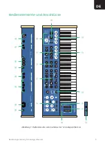
 Bedienelemente und Anschlüsse

Abbildung 1: 

s

q

y

w

e

a

r

t

t

t

u

i

o

d

f

g

h

j

k

l

;

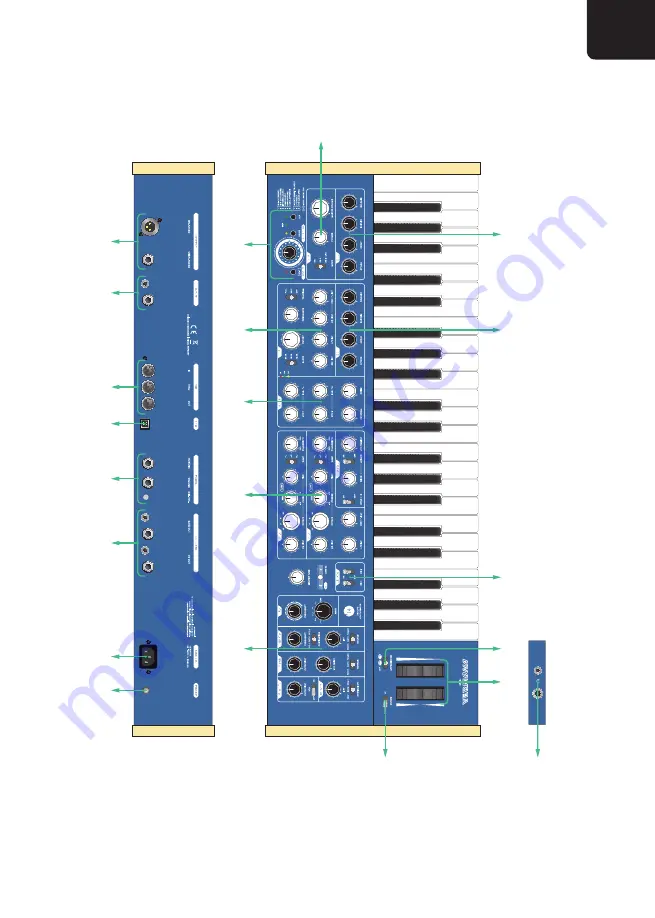
Bedienelemente und Anschlüsse des ’14 Analogsynthesizers

Summary of Contents for '14 Analogsynthesizer

Page 1: ...Deutschlands mit seiner langen Historie im traditionellen Musikinstrumenten Handwerk gew hnt sind Mit Eifer und Herzblut machten wir uns an die Verwirklichung des schlicht 14 getauften Projekts Bernd...

Page 2: ...er Tonh he 13 Oszillator Synchronisation 14 Glide 14 Der Mixer 15 Das Filter 16 Cutoff Resonance und Tracking 16 Modulation der Cutoff Frequenz 17 Der Verst rker 18 Modulation und Spielhilfen 19 Die H...

Page 3: ...equenzen 31 Abspielen von Sequenzen 31 Arpeggiator ber MIDI senden 32 Interner Taktgeber und MIDI Clock 33 MIDI Clock aktivieren 33 Den internen Taktgeber als MIDI CLOCK ausgeben 34 MIDI Einstellungen...

Page 4: ...s trockenes Tuch wie es dem Ger t beiliegt Verwende keine scharfen Reinigungsmittel oder Wasser Betrieb in der N he explosionsf higer Stoffe Der 14 Analogsynthesizer darf wie alle elektrischen Apparat...

Page 5: ...ags zu vermeiden d rfen keine Service oder Wartungsarbeiten durchgef hrt werden die nicht ausdr cklich als solche gekennzeichnet sind VOR DEM FFNEN DES GER TS IST UNBEDINGT DAS NETZKABEL VOM GER T ZU...

Page 6: ...schlie en deshalb bitten wir dich das Ger t und die Verpackung nach Erhalt selbst noch einmal gr ndlich in Augenschein zu nehmen Im Falle eines Schadens hilft eine schnelle Mitteilung an uns das Probl...

Page 7: ...ind mit dem Symbol H beschriftet und k nnen gleichzeitig benutzt werden Die Lautst rke der beiden Kopfh rerausg nge wird gemeinsam aber unabh ngig von den Line Ausg ngen mit dem PHONES Regler in der V...

Page 8: ...s Das interne Netzteil kann mit Wechselspannungen zwischen 90 und 240 Volt 50 60 Hz betrieben werden Eine manuelle Anpassung der Spannung am Ger t ist nicht notwendig und die Anschaffung von Step Up o...

Page 9: ...9 Bedienungsanleitung 14 Analogsynthesizer DE Bedienelemente und Anschl sse Abbildung 1 s q y w e a r t t t u i o d f g h j k l Bedienelemente und Anschl sse des 14 Analogsynthesizers...

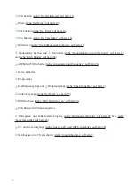
Page 10: ...te 24 i ARPEGGIATOR Schalter siehe Arpeggiator und Sequenzer auf Seite 26 o Oktav Schalter a Programmer s Kopfh rerausg nge und d Hauptausg nge siehe Inbetriebnahme auf Seite 7 f Audio Eing nge siehe...

Page 11: ...en bis auf einige zus tzliche Merkmale von VCO 2 ber den gleichen Funktionsumfang Wir beschreiben identische Bedienelemente und Funktionen deshalb f r VCO 1 und VCO 2 gemeinsam Einstellen der Tonh he...

Page 12: ...r Oszillator ein symmetrisches Rechteck Bei Rechtsanschlag des Reglers betr gt die Pulsweite 95 Prozent Die Pulsweite kann zus tzlich vom LFO moduliert werden Die Intensit t der Modulation wird f r VC...

Page 13: ...ch Drehen nach rechts wird sie positiv also nach oben moduliert Die Tonh he von VCO 2 kann zus tzlich vom LFO moduliert werden Die Intensit t wird mit dem LFO INT Regler eingestellt Als weitere Modula...

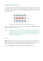
Page 14: ...alter aktiviert die Oszillator Synchronisation H Bei klassischen Sync Sounds sollte die Tonh he des Slave Oszillators beim 14 Analogsynthesizer also die von VCO 2 h her als die des Masters und als Wel...

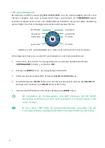
Page 15: ...uf den Klangcharakter des Filters Aus diesem Grund haben wir dem 14 Analogsynthesizer eine Pegelanzeige bestehend aus drei LEDs mit den Farben gelb gr n und rot spendiert Sie zeigen von unten nach obe...

Page 16: ...hohen Werten bei denen das Filter straff und kr ftig zupackt RESONANCE regelt die St rke der R ckkopplung des Filterausgangs in den Eingang Je nach St rke dieser R ckkopplung entsteht eine mehr oder w...

Page 17: ...der Modulation durch den LFO Sehr drastische Effekte entstehen durch die Modulation der Cutoff Frequenz durch die Sinus Wellenform von VCO 1 Die Intensit t dieser Frequenzmodulation kurz FM kann manu...

Page 18: ...s In der Position ON ist er permanent eingeschaltet IndenPositionenEG2undEG2 LFOwirddiedynamischeSteuerungdurchdenH llkurvengenerator EG 2 bzw dessen zus tzliche Beeinflussung durch den LFO w hrend de...

Page 19: ...eratoren engl envelope generator EG EG 1 und EG 2 W hrend EG 2 fest dem VCA zugeordnet ist kann EG 1 mehrere Ziele gleichzeitig modulieren unabh ngig voneinander die Tonh hen von VCO 1 und VCO 2 die C...

Page 20: ...gen ber eigene Legato Schalter unterhalb des MASTER TUNE Reglers In ihrer OFF Position wird die jeweilige H llkurve ausnahmslos mit jedem Anschlag einer Keyboard Taste neu gestartet Mit eingeschaltete...

Page 21: ...r Verf gung stehen steigender und fallender S gezahn 1 2 Rechteck 3 Dreieck 4 Sinus 5 und Zufall RND LFO Reset und Synchronisation k nnen ber die EDIT Parameter eingestellt werden LFO Reset Bei aktivi...

Page 22: ...aktivieren deaktivieren 1 Stelle sicher dass sich der 14 Analogsynthesizer im normalen Spielbetrieb befindet ARPEGGIATOR Schalter i in Position OFF 2 Bet tige den EDIT Taster die dazugeh rige LED leu...

Page 23: ...lationsrad TOUCH Aftertouch und BOTH Modulationsrad und Aftertouch H In der Position BOTH addieren sich die mit dem Modulationsrad und Aftertouch erzeugten Werte Die maximale Intensit t kann damit dop...

Page 24: ...e Quelle f r die Intensit tssteuerung Zur Auswahl stehen WHEEL Modulationsrad TOUCH Aftertouch und BOTH Modulationsrad und Aftertouch VCF FM INT regelt die FM Intensit t bei maximaler Aussteuerung der...

Page 25: ...ufgedreht wird desto st rker ist die Wirkung der Anschlagdynamik auf die Filterfrequenz Lautst rkepedal An die VOLUME Klinkenbuchse j auf der R ckseite des 14 Analogsynthesizers kann ein Fu schweller...

Page 26: ...asten der Klaviatur abgespielt und transponiert werden Im Arpeggiator und Sequenzer Modus werden die wichtigsten Einstellungen mit dem Auswahlrad und den dazugeh rigen Tastern vorgenommen Es gilt jewe...

Page 27: ...n Arpeggio aus 60 mal der gleichen Note mit jeweils unterschiedlichen Anschlagst rken bestehen H Es k nnen mehrere Pausen nacheinander eingef gt aber niemals am Beginn eines Arpeggios platziert werden...

Page 28: ...ion 4 5 und 6 des Auswahlrads ausgew hlt 4 DOWN 5 DOWN 1 Oktave 6 DOWN 2 Oktaven UP DOWN Die auf der Klaviatur und mittels Haltepedal gehaltenen T ne werden auf und abw rts gespielt wobei die erste un...

Page 29: ...Positionen 13 und 14 des Auswahlrads ausgew hlt 13 ALTERNATE UP 14 ALTERNATE DOWN Klingt kompliziert Hier ein Beispiel Wenn die Tasten C E G H gehalten werden werden sie folgenderma en abgespielt ALTE...

Page 30: ...kein MIDI Clock Signal bleibt der Arpeggiator stehen Zur Anzeige des gew hlten Teilverh ltnisses blinkt die LED in diesem Fall wiederkehrend ein zwei oder dreimal ohne Bezug zur Clock siehe MIDI Clock...

Page 31: ...UE Taster blinkt nun unabh ngig von der eingestellten Notenl nge 2 W hle mit dem Auswahlrad den gew nschten Speicherplatz 1 16 aus 3 Speichere die Sequenz durch Bet tigen des VALUE Tasters Um den Vorg...

Page 32: ...14 Analogsynthesizer im normalen Spielbetrieb befindet ARPEGGIATOR Schalter i in Position OFF 2 Bet tige den EDIT Taster die dazugeh rige LED leuchtet 3 W hle mit dem Auswahlrad EDIT Parameter 5 SEND...

Page 33: ...ausgew hlt werden Dazu muss EDIT Parameter 3 INTERNAL CLOCK deaktiviert werden F hre dazu die folgenden Schritte aus 1 Stelle sicher dass sich der 14 Analogsynthesizer im normalen Spielbetrieb befinde...

Page 34: ...der 14 Analogsynthesizer im normalen Spielbetrieb befindet ARPEGGIATOR Schalter i in Position OFF 2 Bet tige den EDIT Taster die dazugeh rige LED leuchtet 3 W hle mit dem Auswahlrad EDIT Parameter 4...

Page 35: ...hle mit dem Auswahlrad den gew nschten Parameter aus die gelbe LED ber dem VALUE Taster beginnt zu blinken 1 EDIT PARAMETER 1 MIDI IN CHANNEL zum Einstellen des MIDI Eingangskanals 2 EDIT PARAMETER 2...

Page 36: ...EGGIATOR Schalter i in Position OFF 2 Bet tige den EDIT Taster die dazugeh rige LED leuchtet 3 W hle mit dem Auswahlrad EDIT Parameter 6 LOCAL OFF MODE aus 4 Durch Bet tigen des VALUE Tasters wird der...

Page 37: ...ss sich der 14 Analogsynthesizer im normalen Spielbetrieb befindet ARPEGGIATOR Schalter i in Position OFF 2 Bet tige den EDIT Taster die dazugeh rige LED leuchtet 3 W hle mit dem Auswahlrad EDIT Param...

Page 38: ...en Tastenstatus als GATE Signal mit einer Spannung von 10 V aus Spitze bzw eine Steuerspannung f r das Modulationsrad Ring 0 5 V Die Buchsen sind wie folgt belegt Abbildung 10 tip ring Modulationsrad...

Page 39: ...its historical background of building traditional musical instruments With great commitment and enthusiasm we started realizing this project simply called 14 Unfortunately Bernd Haller founder of HDB...

Page 40: ...th 50 Pitch modulation 51 Oscillator synchronization 52 Glide 52 Mixer 53 Filter 54 Cutoff resonance and tracking 54 Cutoff modulation 55 Amplifier 56 Modulation and expression controls 57 Envelope ge...

Page 41: ...ces 69 Playback of sequences 69 Sending arpeggios via MIDI 70 Internal clock and MIDI clock 71 Activating MIDI clock 71 Sending the internal clock as MIDI clock 72 MIDI settings 73 Setting the MIDI in...

Page 42: ...ods The 14 Analogsynthesizer shall not be used near easy flammable or explosive goods like any electric unit Dampness The 14 Analogsynthesizer shall not be used in damp or wet places This includes hum...

Page 43: ...ONNECT THE POWER CORD BEFORE OPENING THE UNIT Do not replace components with the power cord being connected DUE TO THE RISK OF INJURY IT IS PROHIBITED TO INSTALL ADDITIONAL COMPONENTS OR MODIFY EXISTI...

Page 44: ...tation Therefore we ask you to take a careful look at the unit when unpacking Do not hesitate to contact us for help should there be anything unusual with the unit or its packaging You will find the f...

Page 45: ...th the symbol H and can be used simultaneously The level of both headphone outputs is commonly set using the PHONES control in the VCA section r However its level is independent from the level control...

Page 46: ...gsynthesizer The internal power supply can work with alternating currents between 90 and 240 volts and 50 60Hz Manual adaption of the current for the unit is not necessary Therefore there is no need p...

Page 47: ...47 User Guide 14 Analogsynthesizer EN Controls and connections Figure 1 s q y w e a r t t t u i o d f g h j k l Controls and Connections of the 14 Analogsynthesizer...

Page 48: ...ge 62 i ARPEGGIATOR selector switch see Arpeggiator and sequencer on page 64 o OCTAVE switch a Programmer s Headphone outputs and d Main outputs see Startup on page 45 f External Inputs see Mixer on p...

Page 49: ...tional features of VCO 2 Therefore we will describe identical control elements and functions for VCO 1 and VCO 2 commonly Adjusting pitch By using the three control elements OCTAVE COARSE and FINE you...

Page 50: ...ymmetrical square Set fully to the right the pulse width is at 95 percent In addition the pulse width can be modulated by the LFO The modulation intensity is commonly adjusted for VCO 1 and VCO 2 usin...

Page 51: ...tion turning right introduces a positive upwards pitch modulation In addition the pitch of VCO 2 can also be modulated by the LFO Adjust the intensity using the LFO INT control Another modulation sour...

Page 52: ...VCO 2 The SYNC 1 2 switch activates the oscillator synchronization H For classic sync sounds set VCO 2 s pitch the synchronized oscillator higher than VCO 1 and select square as waveform By modulatin...

Page 53: ...y influence the sonic character of the filter For this reason we have equipped the 14 Analogsynthesizer with a level display consisting of three LEDs in yellow green and red These display the followin...

Page 54: ...ght and more powerful RESONANCE adjusts the amount of feedback of the filter output back into its input Depending on the setting the resonance parameter may slightly color or heavily accent the sound...

Page 55: ...modulation intensity by the LFO Drastic effects can be created by modulating the cutoff frequency by the sine waveform of VCO 1 The intensity of the frequency modulation short FM can be manually set a...

Page 56: ...ON the VCA is permanently active When set to positions EG 2 and EG 2 LFO the VCA is dynamically controlled by envelope generator EG 2 resp by an additional modulation by the LFO during the sustain ph...

Page 57: ...nd EG 2 While EG 2 always controls the VCA EG 1 is capable of modulating several targets simultaneously the pitches of VCO 1 and VCO 2 independently the filter s cutoff frequency the modulation amount...

Page 58: ...ches below the MASTER TUNE control When set to their OFF position the corresponding envelope generator is always restarted whenever a new note is being played With legato being enabled the envelope ge...

Page 59: ...ilable waveforms are rising and falling sawtooth 1 2 square 3 triangle 4 sine 5 and random RND LFO reset and LFO synchronization can be adjusted using the EDIT parameters LFO reset With EDIT parameter...

Page 60: ...the 14 Analogsynthesizer is in standard play mode ARPEGGIATOR switch i set to OFF 2 Enter the edit mode by pressing the EDIT button the corresponding LED will be lit 3 Use the select dial to select th...

Page 61: ...ouch and BOTH modulation wheel and aftertouch H When set to BOTH the values generated by the modulation wheel and the aftertouch are summed up For this reason the maximum intensity can be twice as hig...

Page 62: ...ntrols the intensity Available choices are WHEEL modulation wheel TOUCH aftertouch and BOTH modulation wheel and aftertouch VCF FM INT adjusts the FM intensity if modulated by the source WHEEL TOUCH f...

Page 63: ...plied The more this control is turned up the stronger the influence of the velocity towards the filter frequency Volume pedal You may connect a pedal to the VOLUME jack j input on the 14 Analogsynthes...

Page 64: ...e saved as sequences These can be started and transposed using the keyboard In ARP and SEQ mode the relevant functions are set by the select dial and the corresponding buttons There are inverted label...

Page 65: ...consist of 60 identical notes with different velocities H Several pauses may be inserted in a row but can never be placed in the beginning of an arpeggio Pattern The pattern determines in which order...

Page 66: ...selected by positions 4 5 and 6 of the select dial 4 DOWN 5 DOWN 1 octave 6 DOWN 2 octaves UP DOWN The notes being played on the keyboard or being held using the sustain pedal will be played back upw...

Page 67: ...ositions 13 and 14 of the select dial 13 ALTERNATE UP 14 ALTERNATE DOWN Sounds complicated Here s an example Holding the keys C E G B will lead to the following playback ALTERNATE UP C G E B 1st posit...

Page 68: ...lay the clock division currently selected the LEDs blinks repeatedly once twice or three times in unrelated speed to the clock see Activating MIDI clock on page 71 Note length The length of the notes...

Page 69: ...button will blink depending on the note length being set 2 Use the select dial to select the desired storage location 1 to 16 3 Save the sequence by pressing the VALUE button To terminate the procedu...

Page 70: ...gsynthesizer is in standard play mode ARPEGGIATOR switch i set to OFF 2 Enter the edit mode by pressing the EDIT button the corresponding LED will be lit 3 Use the select dial to select the EDIT param...

Page 71: ...ock can be selected To do so deactivate the EDIT parameter 3 INTERNAL CLOCK Carry out the following steps to do so 1 Make sure the 14 Analogsynthesizer is in standard play mode ARPEGGIATOR switch i se...

Page 72: ...thesizer is in standard play mode ARPEGGIATOR switch set to OFF 2 Enter the edit mode by pressing the EDIT button the corresponding LED will be lit 3 Use the select dial to select the EDIT parameter 4...

Page 73: ...3 Use the select dial to select the desired parameter the yellow LED above the VALUE button will start blinking 1 EDIT PARAMETER 1 MIDI IN CHANNEL sets the MIDI input channel 2 EDIT PARAMETER 2 MIDI I...

Page 74: ...mode ARPEGGIATOR switch i set to OFF 2 Enter the edit mode by pressing the EDIT button the corresponding LED will be lit 3 Use the select dial to select the EDIT parameter 6 LOCAL OFF MODE 4 Pressing...

Page 75: ...re the 14 Analogsynthesizer is in standard play mode ARPEGGIATOR switch i set to OFF 2 Enter the edit mode by pressing the EDIT button the corresponding LED will be lit 3 Use the select dial to select...

Page 76: ...l with a voltage of 10 V tip as well as a control voltage for the modulation wheel ring 0 5 volts The jacks are assigned as follows Figure 10 tip ring Modulation Wheel GATE GATE OUT assignment CV OUT...

Reviews: