background image

To Table of Content

MIDI Functions

The DRM1 MKIV receives MIDI notes, including the corresponding velocity data, via the MIDI-In 
and USB ports. This way, its sounds can be played dynamically. Trigger impulses, received at the 
optional trigger inputs, will be converted into MIDI note data plus velocity values and transmitted 
via MIDI-Out and USB ports. Any other MIDI data, such as controller data, will not be  processed by 
the DRM1 MKIV.

Assigning MIDI channel and note number to individual 
instruments

1.  Press and hold the 

TRIG

 button 

q

 of the instrument channels CLAP and DRUM 1 simultaneously. 

The DRM1 MKIV is now in Learn mode. To confirm your choice, Drum 1 will generate a single 
trigger signal (Drum 1 sounds and its TRIG LED lights up). 

2.  Now, press any 

TRIG

 button 

q

 to select the desired instrument (no audible or visual response 

this time).

3.  Send  a  MIDI  note  to  the  DRM1  MKIV  (e.  g.  from  your  attached  MIDI  keyboard).  This  note 

number as well as the active MIDI channel will now be assigned and stored.

4.  Repeat steps 2 and 3 to assign further instrument channels. By using this procedure, you can 

assign different MIDI channels to the instruments of your DRM1 MKIV.

5.  Press and hold the 

TRIG

 button 

q

 of the instrument channel CLAP. This will exit Learn mode 

(again, no audible or visual response this time).

Assigning MIDI channel and note numbers to all 
instruments at once (automatic assignment)

1.  Press and hold the 

TRIG

 button 

q

 of the instrument channels CLAP and DRUM 1 simultaneously. 

The DRM1 MKIV is now in Learn mode. To confirm your choice, Drum 1 will generate a single 
trigger signal (Drum 1 sounds and its TRIG LED lights up)

2.  Now, send a sequence of eight MIDI notes to the DRM 1 MKIV, e.g. by pressing keys on an 

attached MIDI keyboard.

The first MIDI note received will set the note number and MIDI channel of the KICK 

instrument channel. Its TRIG LED will briefly light up and the sound is triggered to confirm 

User Manual DRM1 MKIV

EN

19

Summary of Contents for DRM1 MK4

Page 1: ...USER MANUAL DRM1 MKIV...

Page 2: ...ue to significant historical and political changes This product was introduced many years ago but the DRM1 is still in production Why that is Simply because there are still musicians around who do not...

Page 3: ...nt Channels of the DRM1 MKIV 11 KICK 11 DRUM 1 DRUM 2 13 MULTI 14 SNARE 15 HI HAT 1 HI HAT 2 16 CLAP 17 MIDI Functions 19 Assigning MIDI channel and note number to individual instruments 19 Assigning...

Page 4: ...e the obsolete outlet 8 Protect the power cord from being stomped on squeezed or pinched particularly near the plugs mains outlets and the point where it protrudes from the device 9 Use only accessori...

Page 5: ...1 MKIV is wired in accordance with the local electrical safety certificates and inspected by a qualified electrician Do not install the DRM1 MKIV in hot humid or excessively dusty locations exposed to...

Page 6: ...esk and or an amplifier After connecting the module to a mains outlet socket using the supplied lead set up audio and MIDI connections as follows Setting up audio connections CONNECT FIRST AND THEN TU...

Page 7: ...is to trigger the instrument sounds of your DRM1 MKIV to the DRM1 MKIV s MIDI IN socket s Trigger devices can be a suitably equipped groove box a hardware sequencer the MIDI output of a software sequ...

Page 8: ...rument channel w Sound shaping parameters see The Instrument Channels of the DRM1 MKIV on page 11 e PAN and VOLUME channel volume and panning see Sound Generation on page 10 r OUT INSERT individual ou...

Page 9: ...optional on page 23 o Main outputs OUTPUT LEFT and OUTPUT RIGHT Please refer to page 6 a USB port sends and receives MIDI data and receives firmware updates Please refer to page 7 and MIDI Functions o...

Page 10: ...sic units but still there is a lot more to it One thing can certainly be claimed The DRM1 MKIV is all original sounding and not a clone trying to reproduce eight or nine classic sounds Let s have a lo...

Page 11: ...alf of the control s travel allows for creating punchy kick drums for dance music When moving away from the center setting of the control single kicks will make decay times increase significant ly The...

Page 12: ...itional rawness and depth is imparted to the sound At higher values the sound will start to get overdriven and distorted rendering an external overdrive or distortion pedal redundant if you want to cr...

Page 13: ...modulate the pitch downwards Turning the control counterclockwise from the center position will invert modulation resulting in ascending pitch This modu lation interacts with the DECAY setting ATTACK...

Page 14: ...center position turn clock wise to modulate pitch downwards Turning the control counterclockwise from the center position will invert modulation resulting in ascending pitch ATTACK adds a short fixed...

Page 15: ...ter will only be audible when NOISE is active NOISE adjusts the volume of the noise component of a sound That way the snare will gain more girth and consequently sound more authentic When this control...

Page 16: ...DECAY sets the release time or the duration of a sound FILTER sets the cutoff frequency of the low pass filter coloring the overall sound of the channel BEND adjusts the amount of an optional modulat...

Page 17: ...the sound being governed by the DECAY control To toggle between the trigger modes keep TRIG q depressed for approx one second The corresponding LED will light up briefly to confirm the mode of operat...

Page 18: ...he effect is subtile and will only be audible if the NOISE knob is turned up NOISE adjusts the amount of noise that is blended with the claps Without adding a bit of NOISE the claps will sound quite a...

Page 19: ...MKIV e g from your attached MIDI keyboard This note number as well as the active MIDI channel will now be assigned and stored 4 Repeat steps 2 and 3 to assign further instrument channels By using thi...

Page 20: ...ither HI HAT instrument channels The note number transmitted to the HI HAT instrument assigns the open hi hat cymbal sound The closed hi hat is automatically assigned to the note number two semitones...

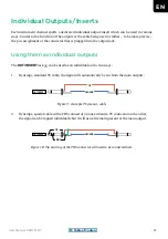
Page 21: ...ual outputs The OUT INSERT jack r can be used as an individual out in two ways 1 By using a standard TS cable the signal will automatically be cut from the main outputs Figure 9 OUT INSERT GROUND TIP...

Page 22: ...o so use a so called insert cable Figure 11 GROUND OUT INSERT GROUND TIP RING SEND RETURN Insert cable Connect the TRS connector to the OUT INSERT r of the respective instrument channel Connect the se...

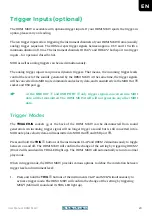
Page 23: ...PORT a only trigger signals converted into MIDI data will be transmitted The DRM1 MKIV itself will not generate any other MIDI data Trigger Modes The TRIGGER IN sockets y at the back of the DRM1 MKIV...

Page 24: ...iggers 5V will produce a constant accent of 11V The MIDI velocity value transmitted will constantly be set to 63 no accent resp 127 with accent DRUM 1 Gate Dynamic Incoming trigger signals between app...

Page 25: ...mplementation 3 x DIN Socket IN OUT THRU USB Port IN OUT Power Supply Mains Voltage 100VAC to 240VAC 50 60Hz Power Consumption 8W Dimensions and Weight Dimensions Desktop 483mm x 225mm x 125mm 19 x 8...

Page 26: ...HDB electronic GmbH Badesteig 20 08258 Markneukirchen GERMANY Fon 49 0 37422 4027 0 Email info vermona com Web www vermona com...

Reviews: