background image

18

Encore

®

 FlexBurn

® 

2040 Non-Catalytic / Catalytic Wood Burning Stove

30005295

Adjust the Leg Levellers 

Lift the stove slightly so there is no weight on the leg while 

making the adjustment.

Reverse the Flue Collar (If necessary)

Reverse the flue collar by removing the two screws that 

attach it to the back of the stove. Be sure the gasket around 

the flue collar opening is in position when you screw the 

collar back onto the stove.

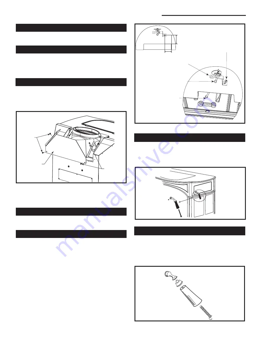
Attach Flue Collar Heat Shield

WARNING:

 The flue collar heat shield must be attached 

to the Encore

®

 stove. Use four #10 sheet metal screws 

supplied to secure the flue collar heat shield to the rear of 

the stove. (Fig. 23) 

ST540
Assembly
handle
11/00

ST540

Fig. 26

  Assemble the front door handle.

ST635

Encore

Install thermostat

handle

2/01

ST635

Fig. 25

  Attach the thermostat handle.

Attach the Damper Handle 

Use the 1/4"-20 x 3" screw to attach the damper handle to 

the damper stub on the left side. 

Attach the Catalyst Temperature Probe

ST1180
flue collar heat shield

Sheet 

Metal 

Screws

Sheet 

Metal 

Screws

Flue Collar 

Heat Shield

ST1180

Fig. 23

  Install flue collar heat shield.

WARNING:

 The flue collar heat shield must be installed 

in all vertical installations. The flue collar heat shield is not 

used when the flue collar is in the rear exit position.

Attach the Primary Air Thermostat Handle 

The primary air thermostat handle is the smaller of the 

two black handles.  Secure the handle to the stub on the 

right side of the stove with an  8-32 x 2" slot head machine 

screw. (Fig. 25)   

Assemble the Removable Insert Handle

The ceramic removable insert handle opens and closes the 

front doors. Remove after each use, and store it in the handle 

holder behind the right front leg.  Assemble the handle by 

passing the 3

3

8

" screw through the ceramic shaft and into 

the bright metal nub. (Fig. 26) Tighten carefully until snug. 

To install the catalyst temperature probe, remove the 

hole plug from the cast iron wall behind the rear shield 

as shown (Fig. 24) use two #10 sheetmetal screws  and 

bracket supplied, secure the bracket and probe to the 

back of your stove.  Fig. (24) 

1.4"

1.8"

Bracket mounting screw  

hole location

Fold bracket strap 

over catalyst probe 

shaft and secure with 

screw.

Insert catalyst probe 

through sheet metal 

into cast iron back.

Remove hold plug 

from cast iron back.

Insert catalyst  

probe bracket with 

self-drilling screw.

Fig. 24

  Install the Catalyst Temperature Probe

Summary of Contents for Encore Flexburn 2040

Page 1: ...Y INJURY OR EVEN DEATH CONTACT LO CAL BUILDING OFFICIALS ABOUT RE STRICTIONS AND INSTALLATION INSPEC TION REQUIREMENTS IN YOUR AREA Encore FlexBurn Non Catalytic Catalytic Wood Burning Stove Installation and Operating Manual Model 2040 2425 Encore NC Cover 5 05 The French language version of this manual is available online www vermontcastings com La version française de ce manuel est disponible en...

Page 2: ...on limits for wood heaters sold on or after May 15 2015 Under specific test conditions this heater has been shown to deliver heat at rates ranging from 9 900 to 34 000 Btu hr The Encore Model 2040 has been tested and is listed by OMNI Test Laboratories of Portland Oregon The test standards areANSI UL 1482 2011 andANSI UL 737 for the United States and ULC S627 00 for Canada The Encore is listed for...

Page 3: ...g 15 381 mm Height to top of flue collar 25 635 mm Under specific conditions during EPA emissions testing Efficiency determined by CSA B415 10 This value can vary depending on how the stove is oper ated the type and moisture content of the fuel used as well as the design construction and climatic location of your home Figures shown are based on maximum fuel consumption rates obtained under laborat...

Page 4: ...rds are the basis for many national codes They are nationally recognized and are accepted by most local authorities Your local dealer or your local building official may have a copy of these regulations IMPORTANT Failuretofollowtheseinstallationinstruc tions may result in a dangerous situation including a chimney or house fire Follow all instructions exactly and do not allow makeshift compromises ...

Page 5: ...relined for proper stove performance Accessories to help make the connection between stain less steel chimney liners and your Encore are available through your local dealer Chimney Connector Guidelines A chimney connector is the single wall pipe that con nects the stove to the chimney The chimney itself is the masonry or prefabricated structure that encloses the flue Chimney connectors are used on...

Page 6: ...h should be no longer than 8 2 4 m In cathedral ceiling installations extend the prefabricated chimney downward to within 8 2 4 m of the stove This will help maintain a good draft by keeping the smoke warm so that it rises readily Wear gloves and protective eyewear when drilling cutting or joining sections of chimney connector Single wall Chimney Connectors Begin assembly at the flue collar of the...

Page 7: ...l lations This information is on Page 9 Wall Pass Throughs Whenever possible design your installation so the connec tor does not pass through a combustible wall If you are considering a wall pass through in your installation check with your building inspector before you begin Also check with the chimney connector manufacturer for any specific requirements Accessories are available for use as wall ...

Page 8: ...nsulated double wall high temperature chimney with an inside diameter the same as the chimney connector at least one inch of solid insulation and a minimum of 9 229 mm air space between the outer wall of the chimney section and combustibles In Canada The Canadian Standards Association has es tablisheddifferentguidelinesforwallpass throughs Figure 10 shows one method in which all combustible materi...

Page 9: ...der the stove and must extend at least 16 not including the ash lip from the front of the stove F Fig 11 and at least 6 from the sides and rear D and E Fig 11 In rear venting configurations floor protection must also extend under the chimney connector and 2 to either side C Fig 11 For the 8 203 mm connector the protector must be a minimum of 12 305 mm wide For the 6 152 mm connector the protector ...

Page 10: ... Stove a Safe Distance From Surrounding Materials Both a stove and its chimney connector radiate heat in all directions when operating and nearby combustible materi als can overheat dangerously if they are too close to the heat source A safe installation requires that adequate clearance be maintained between the hot stove and its connector and nearby combustibles Clearance is the distance between ...

Page 11: ... to reduce clearances is with a wall shield con structed of 24 gauge or heavier sheet metal or of another noncombustible material such as 1 2 13 mm insulation board such as Durock or Wonderboard or common brick laid on flat with the 31 2 90 mm side down Shields must be spaced out from the combustible surface 1 25 mm on noncombustible spacers as in Figure 12 The spacers should not be directly behin...

Page 12: ...p Exit single wall chimney connector heat shield2 vertical flue col lar h s installed Rear Exit No flue collar heat shield Top Exit double wall chimney connector3 vertical flue collar heat shield installed Clearance to Combustible in Front of Stove All Installations S 48 1219 mm The provided rear shroud must be used in all installations The flue collar heat shield must be used in all vertical inst...

Page 13: ...ces Protected Surfaces Top Exit Installations No Stove Heat Shields collar heat shield installed D E F F C C A B J K L L I I G H ST628 Encore Clearance Diagrams 02 01 P Q M N N A N A Top Exit Installations vertical collar heat shield and chimney connector heat shields or double wall connector Rear Exit Installations Clearance Diagrams For use with either 6 or 8 flue collar chimney connector ...

Page 14: ... 572 mm 495 mm 235 mm 470 mm To locate center of flue collar for corner installation add 61 2 165 mm to the clearance distance from stove corner to wall Mark off the resulting distance from the corner along both walls Next measure the same distance from these two points out from the walls These last two measurements will meet at a point representing the center of the flue collar Refer to the dia g...

Page 15: ... with codes Refer to Special Installations ST498 48 1220 mm ST497 Defiant wall shield A 11 00 48 1220 mm Fig 15 Parallel installation vertical chimney connector two wall shields Reduced clearances for both rear and side walls Wall shields may meet at corner if desired Shielding for connector is centered behind connector ST497 48 1220 mm 48 1220 mm ST499 Defiant Wall Shield C 11 00 ST499 Fig 17 Cor...

Page 16: ...ORY BUILT CHIMNEYS Floor protection referenced on Page 10 must be followed 8 Use silicone to create an effective vapor barrier at the location where the chimney or other component pen etrates to the exterior of the structure 9 Follow the chimney and chimney connector manufac turer s instructions when installing the flue system for use in a mobile home NOTE Offsets from the vertical not exceeding 4...

Page 17: ...ble Dragging or sliding the stove especially across rough surfaces can cause the legs to loosen or even break ST858 attach legs 12 05 Leg Bolt and Washer ST858 Fig 20 Attach the stove legs ST564 handle holder 12 13 00 Bottom Heat Shield Door Handle Holder Leg Bolt and Washer ST564 Fig 21 Handle holder and heat shield positions Storing the Handle Use the removable handle to open or close the doors ...

Page 18: ...d WARNING The flue collar heat shield must be installed in all vertical installations The flue collar heat shield is not used when the flue collar is in the rear exit position Attach the Primary Air Thermostat Handle The primary air thermostat handle is the smaller of the two black handles Secure the handle to the stub on the right side of the stove with an 8 32 x 2 slot head machine screw Fig 25 ...

Page 19: ...t shield 6 Fan will not operate until stove reaches approximately 109 F 7 Plug blower cord into a grounded outlet Do not re move ground prong from plug Route power cord to avoid heat from the stove or other damage Do not route cord under or in front of appliance Fig 27 Fan installation Kit 2767 ST848 fan install 6 05 Rheostat Knob Rheostat Snapstat Screws ST848 Hole for Wire Tie to Secure Cable Rh...

Page 20: ...re or emptying the ashes If you install a detector in the same room locate it as far away from the stove as possible Conveniently locate a Class A fire extinguisher to con tend with small fires Be sure the fire extinguisher works and is clearly visible All occupants of the house should know where it is and how it operates Have heavy stove gloves available near the stove Have special safety ac cess...

Page 21: ...ontrols are conveniently located and easy to operate Door Handle ST637 encore Air control 2 01 Low Heat High Heat ST637 Fig 32 The handle may be positioned anywhere between the two extremes for different heat levels ST638 Encore damper control Damper Positions Open Updraft Mode Closed High Efficiency Mode ST638 Fig 33 The damper is either open or closed There are no intermediate positions A Damper...

Page 22: ...600 F 260 315 C half the temperature normally required for unaided secondary combustion The catalytic element is a ceramic honeycomb coated with the catalytic material The element is located in the secondary combustion chamber molded from a special high temperature insulating refractory material The chamber provides the correct environment necessary for secondary combustion of the fuel smoke Closi...

Page 23: ...Protect the Glass Your stove has andirons to keep logs away from the glass panels The andirons are essential to maintain clear fire viewing and should be left permanently in place Since the andirons may slightly hinder refueling through the front doors most stove owners will prefer the convenience of top loading through the griddle Do not place fuel between the andirons and the doors Burn Only Hig...

Page 24: ...ontrol settings as a starting point to help determine the best settings for your installation Each is described as a fraction of the total distance the lever may be moved from right to left Use the Air Control Settings that Work Best for You ST523 Intrepid temp readings 11 00 ST523 Fig 36 Take temperature readings with a thermometer located in the middle of the griddle Surface Thermometer is a Val...

Page 25: ...lit firewood If this is one of the first few break in fires let the fire burn brightly and then let it die out During the break in fires do not let the stove get hotter than 500 F 260 C as measured on an optional stove top thermometer Adjust the air control lever as necessary to control the fire Some odor from the stove s hot metal and the paint is normal for the first few fires NOTE Some chimneys...

Page 26: ...durability Removeashbefore it reaches the top of the ash pan Check the level at least once a day Every few days clear any ash from the outer edges of the firebox Most of the ash will fall through the grate Slice or stir the ash with a shovel or poker so that it falls through the grate slots IMPORTANT Check the level of ash in the ash pan before reloading the stove If the ash level is close to the ...

Page 27: ...his will result in over firing and could cause damage to the stove void the warranty or even lead to a house fire Empty the ash pan regularly typically every one to three days The frequency will vary depending on how you op erate your Encore ash will accumulate faster at higher heat outputs Remove ash frequently and place it outdoors in a metal container with a tight fitting lid Place the closed c...

Page 28: ... outdoors so it takes less heat from the stove to heat it up and keep it warm Chimney Height The common wisdom tells us that a taller flue draws better than a short one This isn t necessarily so If a chimney is tall enough to meet the safety requirements of the 2 3 10 foot rule then adding more height isn t the right answer to a draft problem In fact it could make the problem worse by adding more ...

Page 29: ...red and cracked a piece is the drier it is Dry wood burns readily with a good chimney draft But with modern stoves wood can be too dry and too volatile Smoke and combustible gases can gas out from the wood quickly and densely enough to overload the combustion system If you hear a rumbling or roaring noise like a propane torch from the stove that is a sign that the stove is over firing Back puffing...

Page 30: ...that accumulates on the glass surface should be removed regularly to prevent etching To clean the glass follow this procedure Be sure the glass is completely cool Clean the glass with water or a cleaner made especially for this purpose Do not use abrasive cleaners Use cleaning agents sparingly and be sure to keep them off the outer surfaces of the stove Rinse the glass thoroughly Dry the glass com...

Page 31: ...until the setting is right If additional adjusting of the latch does not enable the door to seal sufficiently in one area try adjusting the gasket in that area Pack more cement or a smaller diameter gasket into the channel beneath the gasket so the main gasket is raised and makes contact with the door frame If this procedure doesn t solve the problem replace the gasket Instructions for gasket repl...

Page 32: ...imney and chimney connector on a regular schedule Clean the system if necessary Failure to keep the chimney and connector system clean can result in a serious chimney fire When wood is burned slowly it produces tar organic vapors and moisture that combine to form creosote The creosote vapors condense in the relatively cool chimney flue of a slow burning fire As a result creosote residue accumulate...

Page 33: ...wear and replace if necessary Remove ashes from the ash pan and replace with a moisture absorbing material such as kitty litter to keep the interior of the stove dry Clean the dust from the inner sides of bottom rear or pipe heat shields if your stove is equipped with them Clean surfaces are better heat reflectors than dirty sur faces Touch up the black paint Inspect for and remove ash build up be...

Page 34: ...ir quickly smoke does not If this test indicates a problem consider other possible fac tors as well such as the weather or a change in the quality of your fuel In warm weather draft is weaker than it is in colder winter weather and fires can burn sluggishly Small hot fires are a good solution under these conditions Burning green insufficiently seasoned wood will result in poorer performance than b...

Page 35: ... up as fast it is likely that the performance change was caused by fly ash deposits on the catalytic element However continue the inspections of the chimney system for a few weeks to ensure that proper performance continues If you continue to find a significant creosote buildup or if you continue to see excessive smoke from the chimney the catalytic element will need to be replaced Contact your ne...

Page 36: ... at any time without notice 56 80 3 21 17 20 19 16 18 58 12 22 63 57 32 38 31 36 39 45 87 27 26 71 72 68 67a 72 40 49 37 81 47 59 30 29 26 28 73 5 70 69 62 61b 79 55 83a 54 52 53 51 49 16 50 27 2 79 10 11 75 48 82 82 14 24 77 76 85 74 23 23 8 25 15 35 41 44 42 6 7 46 43 84 65 65 13 9 33 78 83b 83 86 34 60 1 4 89 90 91 92 93 61a 67b Encore Non catalytic Catalytic Wood Burning Stove Model 2040 Repla...

Page 37: ...r Fireback Refractory 30005248 44 Refractory Inner Cover 30005205 45 Andiron 30002397 46 Refractory Access Cover 30007251 47 Leg Leveller 1201745 48 Ashdoor Handle Shaft 1600622 49 Pawl Assy 30005157 50 Ashdoor 30002392 51 Ashdoor Handle Wood 1600663 52 Ashdoor Hinge Rod 30002473 53 Cotter Pin Ashdoor 30001749 54 Ashdoor Hinge Lower 30002404 55 Ashpan Bracket 1601039 56 Lower Side Bracket 30005268...

Page 38: ... Left Side 30002388 30003052 30006679 30003072 30004876 30002633 30007027 Right Side 30002405 30003053 30006680 30003073 30004877 30002632 30007028 Flue Collar 1305050 30003160 30006683 30003162 30004873 2375050 30007031 Front 30002393 30003054 30006681 30003074 30004878 30002634 30007029 Ashlip 30002402 30003051 30006678 30003071 30004875 30002630 30007026 Left Door Sub Assembly 30003974 30003984...

Page 39: ...ase date 3 Date of failure of catalyst 4 Any relevant information or circumstances regarding determination of failure 5 In addition the owner must return the failed catalyst Exclusions Limitations 1 This product must be installed or serviced by a qualified installer preferably NFI or WETT Canada certified as prescribed by the lo cal jurisdiction It must be installed and operated at all times in ac...

Page 40: ...149 Cleveland Drive Paris Kentucky 40361 www vermontcastingsgroup com ...

Reviews: