26
73D0024
KHLDV Series Gas Fireplace
MILLIVoLt - optIonaL Fan/BLower SySteM
FP2137
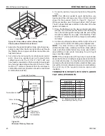
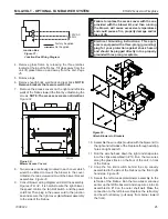
blower access plates
Clip
Firebox
Wall
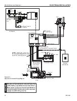
Figure 35 -
Blower Access Covers
FP2137
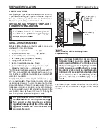
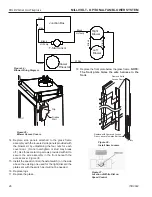
Figure 34 -
Blower Wiring Diagram
Junction Box
Blower
Rheostat
T-Stat Sensor
Right
Blower
Left
Blower
White
Black
Hi-Temp
Black
Black
Hi-Temp
Black
Black
FP2135
blower wiring diagram
Blue
Blue
Boîte de jonction
Ventilateur
Rheostat
Capteur t-stat
Ventilateur
droit
Ventilateur
gauche
Blanc
Noir
Hi-Temp
Noir
Noir
Hi-Temp
Noir
Noir
Bleu
Bleu
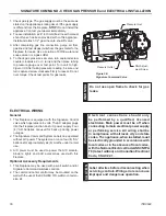
14. Replace side panels attached to the glass frame
assembly with the louvered side panels provided with
the blower kit by unfastening the four nuts for each
cover door. (Do not overtighten or stud may break
off.) Use three metal clip screws provided with kit to
secure the wire assembly in the front beneath the
access cover.
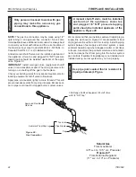
Figure 36
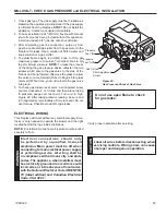
15. Install the speed control (rheostat switch) on the side
above the existing one used for the light (discard the
plate sent with the switch as it will not be needed.
16. Replace logs.
17. Replace the glass.
18. Replace the front plate below the glass frame.
note:
the front plate hides the wire harness in the
front.
Figure 37 -
Location of White Dial on
Speed Control
Figure 36 -
Install New Louvers
FP2234
install louvers
1/09
Remove Solid
Access Door
Replace with Louvered Access
Door, Louvers Towards Bottom
FP2234


