background image

7

3311857

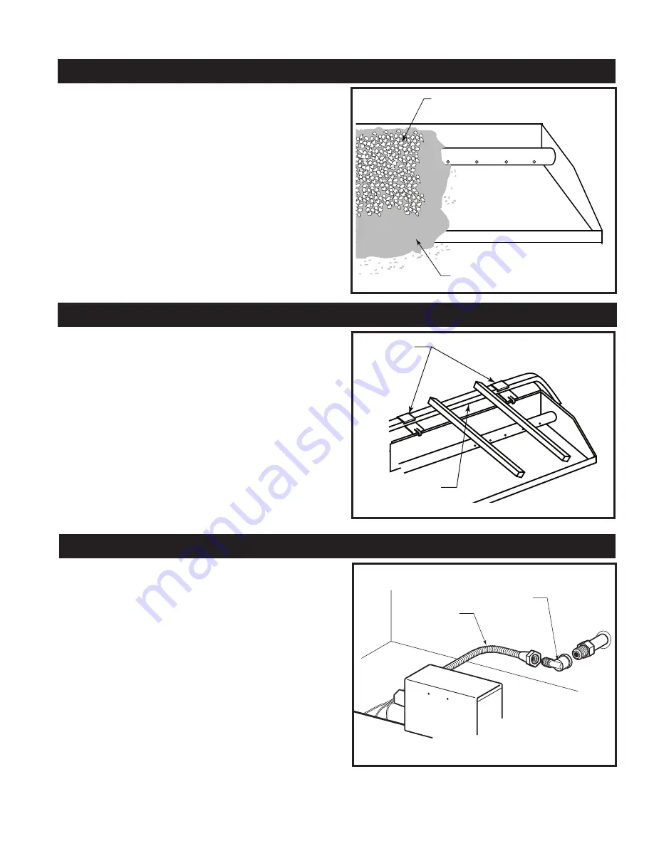
Adding Pan Material

1.  Open the bag of Vermiculite and spread it 

evenly across the Burner Pan, to the top, as 
shown in Figure 5. You may overflow the front 
and sides of the pan to cover the entire pan 
and connecting hardware.

2.  Next, open the bag of Glowing Embers and 

place them on top of the Vermiculite, evenly 
across the Burner Pan.  Be sure to separate 
the Glowing Embers into very small pieces 
before placing them.

Connection To Gas Supply

1.  Hook the U-Shaped part of the Grate Clips over 

the back horizontal bar of the Grate, as shown 
in Figure 6. Repeat with the other Clip.

2.  Slide the rear edge of the burner pan into the 

three-pronged slot in the front edge of the grate 
clip, as shown in Figure 6. 

1.  Center the burner pan from left to right in the 

fireplace and with the back of the grate against 
the back wall of the fireplace.

2.  Attach the Gas Supply Fitting onto your fire-

place’s gas supply pipe. Remember to use pipe 
thread sealant or teflon tape on this connection.

3.  Attach one end of the Flexible Gas 
4.  Connector to the brass  fitting on the back of 

the control valve, as shown in Figure 7.

5.  Attach the other end of the Gas Connector to 

the flared side of the Gas Supply Fitting.

Grate Clip Installation

LG216

ASHK

pan material

11/29/01   djt

Figure 5

Vermiculite 

Glowing Embers

LG216

LG216

grate clip

11/29/01   djt

Figure 6

Grate  Clip

Back Bar Of Grate

LG217

Flexible Gas 

Connector

Figure 7

Gas Supply Fitting

LG218

Summary of Contents for SA18SHKRN

Page 1: ...A18SHKRP SA24SKHRN SA24SHKRP SA30SKHRN SA30SKHRP ATTENTION Installation service and repair of this ap pliance must be performed by a qualified installer service agency company or gas supplier experienced with this type of gas appliance INSTALLER Read these instructions completely and care fully prior to beginning installation After instal lation leave these instructions with the owner OWNER Read th...

Page 2: ...2 psig 3 5 kPa Component Parts Only factory authorized components listed in these instructions may be used in accordance with the manufacturer s instructions and all codes and requirements of the authority hav ing jurisdiction Any modifications to this kit or use of unauthorized components or accessory items will void the manufacturer s warranty and may result in a hazardous condition WARNING Due t...

Page 3: ...lace supply tanks inside any structure G Never use sand or other dense pan material with propane gas use vermiculite only H Be sure to apply pipe joint compound to all non flared threaded connections involved in this installa tion to avoid possible gas leaks Compounds used in liquid propane applications must be resistant to the action of that gas I Always test for leaks using a soapy solution NEVER...

Page 4: ...g codes Check with your local building department Does your fireplace have a wire mesh screen in place Pre Installation Checklist Yes No Minimum Clearances Specifications Natural Gas Units Propane Gas Units Size Btu hr Back Front Depth Height Size Minimum Maximum 18 45 000 16 33 15 18 51 sq in 5 5 w c 14 0 w c 3 5 w c 24 60 000 20 36 15 18 51 sq in 5 5 w c 14 0 w c 3 5 w c 30 60 000 27 39 15 18 51 s...

Page 5: ...end of the Damper Lock ing Bracket If this is the case use the Damper Stop as a template to drill two 2 1 8 holes in the Damper Locking Bracket to mount the Damper Stop NOTE Your gas log set is assembled at the factory to be installed in a fireplace plumbed with the gas on the right side facing If your fireplace is plumbed with the gas on the left side you will need to run a flex ible connector or as...

Page 6: ... so that the damper plate will remain fully open The proper finished installation of the Damper Clamp is shown in Figure 4 If the bolt fails to block the damper in an open position the damper should be removed from the chimney To check your vent for proper drafting Light a tightly rolled newspaper on one end and place it at the inside front edge of the fireplace Observe the smoke and be sure the ven...

Page 7: ... burner pan into the three pronged slot in the front edge of the grate clip as shown in Figure 6 1 Center the burner pan from left to right in the fireplace and with the back of the grate against the back wall of the fireplace 2 Attach the Gas Supply Fitting onto your fire place s gas supply pipe Remember to use pipe thread sealant or teflon tape on this connection 3 Attach one end of the Flexible Gas...

Page 8: ...ocedure until no bubbles appear in the soap solution Remember to test all joints WARNING DO NOT USE AN OPEN FLAME TO TEST FOR LEAKS NOTE Always perform a leak test any time the appliance has been moved or disconnected from the gas supply line Remote Installation Connect remote GWSK or MRC 1 2 3 wires to ON OFF RS switch Fig 8 If the MRC remote is used the receiver can be placed to the front right ...

Page 9: ...eve your desired flame pattern Be sure you leave as much open space between the logs as possible to minimize flame impinge ment and sooting 3 Open the bag of lava rock and spread the rocks onto the fireplace floor around the burner pan for decorative purposes Available Log Sets LG330 18 Standard round log set 4 04 djt LG330 18 Standard Round Log Set 24 Standard Round Log Set LG331 LG331 24 Standard ro...

Page 10: ...dard Split Log Set LG334 LG335 30 Standard split log set 4 04 djt 30 Standard Split Log Set LG335 LG336 18 Standard combo log set 4 04 djt 18 Standard Combination Log Set LG336 LG337 24 Standard combo log set 4 04 djt 24 Standard Combination Log Set LG337 LG338 30 Standard combo log set 4 04 djt 30 Standard Combination Log Set LG338 ...

Page 11: ...tay lit after several tries turn the gas control knob to OFF and call your service technician or gas supplier 8 Turn gas control knob counterclockwise to ON CAUTION Be sure ON OFF RS switch is in the off middle position Also the GWSK should be in the OFF position and or the remote should be in the OFF position before turning the control knob ON If pilot goes out repeat steps 4 and 5 9 Turn ON OFF ...

Page 12: ... on Page 4 Incorrect Orifice used Check the orifice size on Page 15 to see if you installed the correct orifice into the set Burner Is Excessively Noisy Please note The movement and combustion of gas will create low unavoidable levels of noise Passage of air gas across irregular surfaces There may be burrs paint or other blockages on the burner bar ports Check these ports and remove any blockage Exce...

Page 13: ...r customer service line Incorrect Pilot Orifice Make sure the correct Pilot Orifice is installed green for Natural Gas red for propane Incorrect gas supply pressure Make sure your gas pressure meets the specifications outlined on Page 4 Flames at the Air Mixer Flashback Propane Gas Only Correct Orifice used Check the chart on Page 15 to see if you used the correct Orifice Also be sure you only used the...

Page 14: ...20007269 3 Cast Front Grate w Clips CIGF 18 CIGF 24 CIGF 30 4 Grate Clip Fettel 3304311 3304311 3304311 5 Screw Grate Clip 3309078 3309078 3309078 6 Bag of Lava Rock 8lbs 4310010 4310010 4310010 7a Bag of Sand Natural Gas Models ONLY 4310006 4310006 4310006 7b Bag of Vermiculite 4310008 4310008 4310008 8 Bag of Glowing Embers 4310001 4310001 4310001 9 Damper Stop for CFM Corporation Fireplaces ONL...

Page 15: ...9 41 Log Set Replacement Parts Ref Description Log Sets 1 18 Standard Round Log Set 20007854 1a 24 30 Round Right Front 20007833 1b 18 Round Left Front 20007835 1c 24 30 Round Front Cross Log 20007834 1d 18 24 30 Cross Log 20007837 1e 18 Cross Log 20007836 1f Top Log 20008335 2 24 Standard Round Log Set 20007855 2a 24 30 Round Left Front 20007839 2b 24 30 Round Right Front 20007838 2c 24 30 Back L...

Page 16: ...4b 4c 4d 4e 4f 4 5 6a 6b 6c 6d 6e 2 6f 2 6 7a 7b 7c 7d 7e 7 8a 8b 8c 8d 8e 8f 8g 8 9a 9b 9c 9d 9e 2 9f 9g 9h 9j 9 CFM Corporation reserves the right to make changes in design materials specifications prices and discontinue colors and products at any time without notice SA18 24 30SHK Series Vented Gas Logs Remote Hearth Kit ...

Page 17: ... Round Front Cross Log 20007806 7e 18 24 30 Cross Log 20007705 8 24 Standard Combination Log Set 20007861 8a 18 24 30 Back Log 20007807 8b 24 Split Right Front 20007808 8c Top Log 3 20008337 8d Top Log 20008336 8e Top Log 20008335 8f 24 30 Cross Log 20007810 8g 24 30 Round Front Cross Log 20007809 9 30 Standard Combination Log Set 20007862 9a 18 24 30 Back Log 20007818 9b 30 Split Left Front 20007...

Page 18: ......

Page 19: ...and components referred to in those paragraphs subject to the following conditions and limitations 1 These warranties are extended only to the Gas Ap pliance installed in the continental United States including Alaska and Canada only if and so long as the accordance with the installation and operating instructions furnished therewith and only if and so long as Gas Appliance is not removed from its...

Page 20: ...410 Admiral Blvd Mississauga Ontario Canada L5T 2N6 905 670 7777 www majesticproducts com www vermontcastings com CFM Corporation ...

Reviews: