SB38 / SB44 Series Woodburning Fireplace
1
87D0057
iNStallatioN preparatioN
18’ Min.
FP1881
single story install
8/08
Chimney Cap
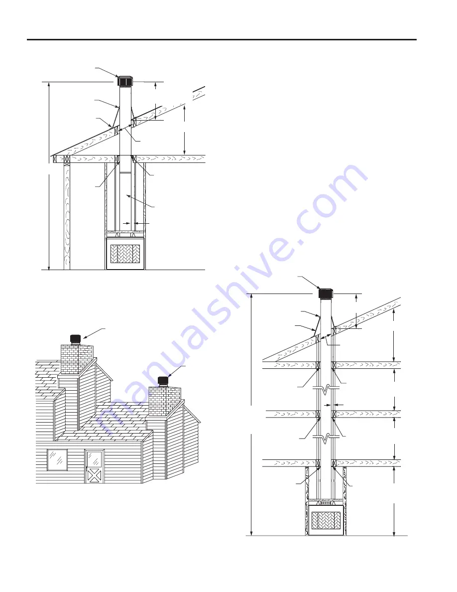
Single Story installation with attic Space
Storm Collar
Flashing
Flue Outlet Height
3’ Min. or ’ Above
any Point within 10’
See Table
1 for Roof
Opening Size
Attic Space
Firestop Spacer
(” Air space
Clearance to
Combustibles)
Chimney
Sections
17”
Square
Opening
in Joist
FP1881
Figure 10
FP1882
chimney location
8/08
Figure 11
Preferred Location
Poor Location
FP188
3 ft. Min.
FP1883
multistory install
8/08
Figure 12
Chimney Cap
Storm Collar
(Included with cap)
Flashing
See Table 1 for
Roof Opening
Size
Attic Space
Firestop
Spacer (”
Air Space
Clearance to
Combustibles)
” Clearance to
Combustibles (Min.)
17” Square
Opening in
Joist
max.
installation
height -
86 ft.
Third Floor
Area
Second
Floor Area
First Floor
Area
Flue Outlet Height
17” Square
Opening in
Joist
17” Square
Opening in Joist
Firestop
Spacer
Firestop
Spacer
FP1883
iNSulatiNg fireplace eNcloSure for
cold climateS
if you live in a cold climate, it is not required but highly
recommended
that you insulate the fireplace enclosure to
eliminate cold air penetration as much as possible.
Insulate base of fireplace with a noncombustible insulation
rated for a minimum of 300° F. Insulating is very important
for outside wall installations over a concrete slab. If fire-
place is installed on a platform, insulation should be placed
on top of the platform before fireplace is set.
Figure 9
When a fireplace is installed in a chase or on an outside
wall, enclosure should be treated like any outside wall in
a home. Insulation should be installed on the inside wall
as well as the outside wall(s). In a chase, it is also a good
idea to install a firestop at the first ceiling level above the
fireplace and enclose the chase with sheeting material.
Insulation may then be installed above sheeting material to
assure the space around the fireplace is totally protected.
Figure 9
cautioN: wheN iNStalliNg a fireplace iN aN
iNSulated eNcloSure, be Sure all required
air SpaceS are maiNtaiNed.
Figures 10 & 12
multiple Story installation
” Minimum Clear-
ance to Combus-
tibles


