background image

87D0058

7

SB50HB Series Woodburning Fireplace

CLearaNCeS

59

56O

58

56O

FP2217  
SB6000 res install 

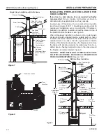
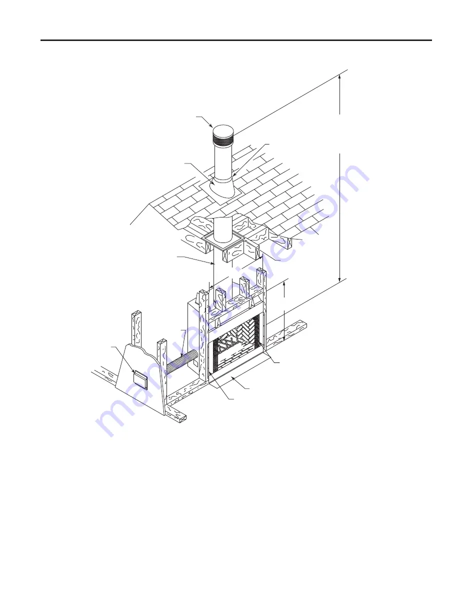
Chimney Cap

Roof Flashing

Chimney Section

Maintain ” Min. Air 

space between Chimney 

and Combustibles

Flexible Duct 

Type FP-4-U

Combustion Air 

Assembly

FP17

Nail to Framing 

Members

Galvanized Metal Strip

CauTION:

 Do not restirict 

side air inlet vents with sur-

round or trim materials

Storm 

Collar

Flue Outlet Height to Floor

18’ = Min. Height (No offsets)

4’ = Min. Height ( 30° Elbows)

30’ = Min. Height (4 30° Elbows)

86’ = Max. Height (Chimney Support 

every 5’)

NOTe:

 If Model WSB60B or GD60B glass doors are to 

be used, noncombustible trim attached to the face of the 

fireplace  must  not  extend  over  the  screen  cover  at  the 

top  of  the  firebox  opening.  The  screen  cover  will  have 

to be removed before the glass doors can be installed. 

Noncombustible trim must not extend over each side of 

the fireplace into the firebox opening to avoid interference 

with installation of the Model WSB60B or GD60B glass 

doors.

Floor

Figure

 3 

SB50HB Fireplace

residential Installation

Summary of Contents for SB50HB

Page 1: ...t properly installed operated and main tained a house fire may result To reduce the risk of fire follow the installation instructions Failure to follow instructions may result in property damage bodily injury or even death Contact local building officials about restrictions and installation inspection requirements in your area Installation Operation and Maintenance Manual for Residential Installat...

Page 2: ...ured You should be aware however that failure to install operate and maintain this or any other factory built fireplace properly can result in a house fire or other occurrences that could cause deaths injuries and property damages It is very important that the persons installing and or supervising the installation of this fireplace have appropriate skills in using the tools and techniques required...

Page 3: ...sembly with a Vermont Castings Group fireplace system not withstanding any independent testing laboratory or other third party approval of such component parts or accessory Any such action may possibly cause a fire hazard SB50HB listed by OMNI Test Laboratories to ANSI UL 127 ULC S610 Standards for Factory built Fireplaces Proposition 65 Warning Fuels used in gas wood burning or oil fired applianc...

Page 4: ...must be installed with clearances to combustible building materials specified in this manual Only parts manufactured by Vermont Castings Group and labeled for use with the fireplace should be used in the installation of this fireplace except for special roof flashings that may be fabricated locally The use of improper parts in the installation can be hazardous and voids the warranty offered by Ver...

Page 5: ...g up to open or pulling down to close the damper When the fireplace is not in use the damper should be closed to prevent cold air form entering the chimney as well as preventing warm air in the room from escaping up the chimney NOTE It is normal for a small amount of smoke to be released from the upper portion of the fireplace the first few times you use your new fireplace This results from an oil...

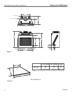
Page 6: ...re 1 3856O 11 1756O 2856O 59 6656O 456O 50 59 11 30 8 38 58 456O 956O 8 1356M 18 539027 SB6000 dims 11 I D Flue 13C O D Flue A B C FP1531 hearth dimensions 9 04 djt Front Width Back Width Depth A B C SB50HB 48 32 22 1219 mm 819 mm 559 mm Hearth Dimensions Figure 2 FP1531 ...

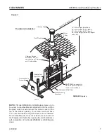
Page 7: ...r 18 Min Height No offsets 24 Min Height 2 30 Elbows 30 Min Height 4 30 Elbows 86 Max Height Chimney Support every 25 NOTE If Model WSB60B or GD60B glass doors are to be used noncombustible trim attached to the face of the fireplace must not extend over the screen cover at the top of the firebox opening The screen cover will have to be removed before the glass doors can be installed Noncombustible...

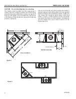
Page 8: ... M M I n 9 8 M i n 1 9 5 6 M M i n 24 Min 156O Air Space Clearance 30 Min FP2219 SB6000 framing Figure 4 Screened Opening Corner Installation Side Wall Installation FP2219 0 FIREPLACE LOCATION Figure 5 Full Protection Corner Flush FP2220 Figures 4 and 5 provide dimensional details of the fireplace required spacing to combustible walls and some suggested fireplace locations When selecting a locatio...

Page 9: ...l FP1880 install prep 8 08 Joist Insulate Same as Ceiling Refer to Notes Firestop Spacer Solid Surface Chimney Cap Flat Chase Top Flashing Chimney Section Insulate Outside Walls of Chase Solid Continuous Surface Insulation Thermal Barriers Outside Base FP1880 NOTES 1 Firestop spacer must be used 2 Local codes may not require firestop ping at the ceiling level for chase in stallation but it is reco...

Page 10: ...estop Spacer FP1883 Figure 9 Insulating Fireplace Enclosure for Cold Climates If you live in a cold climate it is not required but highly recommended that you insulate the fireplace enclosure to eliminate cold air penetration as much as possible Insulate base of fireplace with a noncombustible insulation rated for a minimum of 300 F Insulating is very important for outside wall installations over ...

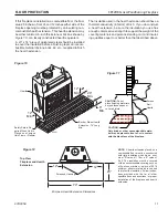
Page 11: ...ensions Screened Opening FP2222 NOTE A hearth extension placed on a combustible floor must be constructed with rigid insulation which has a mini mum R value of 1 16 or a K value of 0 43 The insulation must be covered with a noncombustible covering such as a tile stone marble or a piece of 0 018 minimum sheet metal which is needed to protect the insulation Follow instruc tions provided with the for...

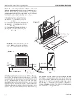
Page 12: ...eveloping the hearth extension materials must be firmly fastened in place Wall ties should be screwed to the face of the fireplace and imbedded in the mortar joints of brick stone or other non combustible materials The metal safety 59 30 58 2856O 20 74 FP2223 hearth protection Figure 13 Metal Safety Strip Combustible Floor FP2223 Hearth Protection WARNING The hearth extension and the metal safety ...

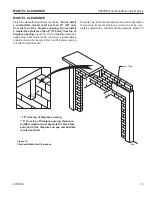
Page 13: ... wall with material of your choice Do not install a combustible mantel shelf less than 18 457 mm from the top of the fireplace opening Do not install a mantel face plate less than 6 159 mm from top of fireplace opening Figure 15 If a combustible material is used below a flat mantel shelf consult your local building codes for minimum clearance from top of fireplace opening to bottom of mantel shelf...

Page 14: ...stible material Surround Face Finished Wall Ledge Bracket Finished Wall Ledge Bracket Combustible Mantel and Trim Mantel Clearance No Noncombustible Facing Material Fireplace Opening Noncombustible Material Combustible Mantel and Trim Mantel Clearance with Noncombustible Facing Material Finished Wall Header Ledge Bracket Noncombustible Material Surround Face Noncombustible Facing Material Fireplac...

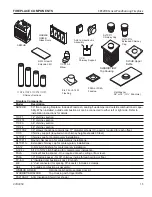
Page 15: ...11CF4 48 chimney section 11CF30 2 30 elbows package contains two 11 diameter elbows One pair is required for each offset 11CS Chimney support required when chimney height exceeds 30 feet SLTCF11 Chimney cap for contemporary installations RLTCF11 Round chimney cap for contemporary installations RLTCF11L Extended chimney cap for contemporary installations 8 6 12 0 6 12 pitch flashing for contemporar...

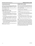
Page 16: ...quire electrically ground ing the fireplace and chimney Chimney Installation In order to assure safe and satisfactory performance of the fireplace it is very important to properly install the chimney This is an important part of the installation and the sections of this manual pertaining to chimney installation should be reviewed very thoroughly For your safety some of the important things to reme...

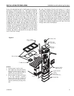
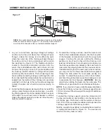
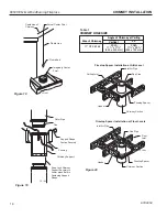
Page 17: ...ng within ten feet as shown in Figure 17 The chimney must not extend more than 90 inches above the roof without additional support 3 To install the chimney sections insert the male end of the flue the smallest diameter pipe into the flue outlet of the fireplace and press down until the snap locks engage Continue the process adding the chimney sections on top of each other until the chimney is at l...

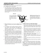
Page 18: ...ely to Lower pipes Before Fastening Support Straps FP1890 FP 548b SHR 5 11 99 djt Angle of Chimney at Ceiling Size of Chimney Vertical 30 11 CF 2 Wall FS2A 1756O x 1756O 445 x 445 mm FS6A 17 6 x 29 6 454 x 753 mm CHIMNEY HOLE SIZE 0 FIRESTOP INSTALL Figure 20 Firestop Spacer Installation at Attic Level Inlet Air Pipe Ceiling Joist Flue Pipe Firestop Spacer Chimney Section Header Firestop Spacer In...

Page 19: ...he required two inch minimum air space clearance to the chimney at the extremities of the offset It is recommended that enclosing material not follow the inclined portions of the chimney 0 ELBOW Figure 21 Inlet Air Pipe Flue All four 4 support straps must be nailed on to fram ing member around the elbow with a minimum of two 2 8 Penny nails per strap NOTE Although both halves of the elbow set may ...

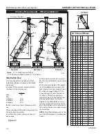
Page 20: ... tion above A Height of the chimney is measured from the hearth to the chimney exit SB50HB Max 86 Min 0 Elbows 18 0 2 Elbows 24 0 4 Elbows 30 0 B Do not use more than 4 elbows per chim ney Attach the straps of the return top elbow to a structural framing member The offset first elbow of any pair does not have straps FP269 C The chimney cannot be more than 30 from the vertical plane in any instal l...

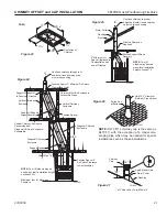
Page 21: ...himney Must Be Enclosed in Accessible Areas Firestop Spacer Diagonal Chimney Enclosure RISE Firestop Spacer 2 Air Space Clearance to Combustibles NOTE Four 4 elbows may be used when toatl installation height exceeds 24 ft Maximum four 4 elbows per Fireplace Offset Max 10 Support Straps Diagonal Chimney Enclosure Vertical Chimney Enclosure Recommended Diagonal Chimney Enclosure Acceptable Fasten Al...

Page 22: ...duct in place and slide the flashing over the chimney Adjust the chimney to assure that the proper minimum clearances are maintained 5 Nail the flashing securely in place with eight nails 6 Seal the crack between the top of the flashing and the chimney with mastic Leave some excess mastic at this area to be used in step eight NOTE Use pliers and wear gloves when performing step seven to minimize t...

Page 23: ...e Roof Line Maintain 2 Minimum Air Space Clearance to Combustibles Above Roof Line Using Tabs Provided Secure Outer Telescoping to the Flat Flashing On Large Chase Tops it is Recommended that Cross Supports be used to Provide Additional Support to Eliminate Sagging of the Flashing 13 Max Space Between Chimney Section and Chase Cover Outer Telescope NOTE Locally built chase flashings must incorpora...

Page 24: ... starting collar to left side of fire place with four 4 sheet metal screws provided NOTE The starting collar extends through the outer fireplace jacket and will seal against the firebox wall when secured as indicated FP1900 0 SECURE OUTSIDE DUCT Step 2 Secure outside duct to starting collar with duct clamp or screws Fireplace Outer Wrap AK4 Combustion Air Kit Shortest Toward Firebox AK4 Mounting P...

Page 25: ...e the cover plate from the 4 inch outlet opening location on the left or right outside of the fireplace DO NOT remove the cover if the outside air will not be connected 2 Place the insulation ring between theAK 4 starting collar and fireplace wall and place the starting collar 4 inch into the hole on the side of the fireplace Fasten it in place with the four sheet metal screws provided 3 Cut a 6 i...

Page 26: ...e people who will be operating them and leave all instruction manuals with the operator of the appliance 2 An approved gas shut off valve must be located outside the fireplace in an area accessible to the users of the fireplace 3 All gas piping and fitting must be either steel or malleable iron Unions must be of the ground joint type 4 Some code authorities prohibit or place restrictions on the us...

Page 27: ... be set in fully open position 0 GAS LINE INSTALLATION Figure 30 Outer Fireplace Wrap Inner Fireplace Wrap Side Brick Hearth Brick Gas Line Access Tube Repack Insulation Around Gas Line Where it Passes Through Gas Line Access Tube for Proper Seal Maintain 1 2 Minimum Air Space Clearance to Combustibles for Gas Line Out to 4 From Side of the Fireplace Combustible Materials May Be Lo cated at Zero C...

Page 28: ...l WSB60 glass doors are to be used noncombustible trim attached to the face of the fireplace must not extend over the screen cover at the top of the firebox opening The screen cover will have to be removed be fore model WSB60 glass doors can be installed Noncombustible trim must not extend over each side of the fireplace into the firebox opening to avoid interference with installation of the model...

Page 29: ...ive but a little combined with other wood goes a long way Start your fire with a mixture of softwood and hardwood then add some fruit or nut wood for nostalgic aroma Since most woods will not burn well when freshly cut the wood you purchase should be reasonably dry The sizes you buy are dictated by the size of your fireplace Purchase logs that will fit when laid across your grate and ask that the ...

Page 30: ... the fireplace is equipped with glass doors close them DO NOT LEAVE CHILDREN OR PHYSICALLY OR MENTALLY HANDICAPPED OR SENILE PERSONS ALONE WITH A BURNING FIREPLACE You ll need a minimum of three logs preferably four to make a good fire Add kindling and new logs as needed to rekindle a dying fire New logs should be added at the rear grate after raking the coals toward the front Do Not Overfire the ...

Page 31: ...ating season to determine if a creosote buildup has occurred If creosote has accumulated it should be removed to reduce the risk of a chimney fire The chimney cap can be removed for inspection maintenance and cleaning by removing three screws from the support legs and lifting upward When the fireplace is first in use inspect the chimney frequently and clean the chimney any time an accumulation is ...

Page 32: ... building 9 Do install the proper chimney cap or chimney housing on the chimney to prevent rain and debris from entering the chimney Maintenance and Safety 10 Do keep all flammable liquids gases and pressurized containers away form the fireplace 11 Do check the fireplace for proper adjustment and operation before leaving it unattended for long periods of time 12 Do inspect and clean the fireplace ...

Page 33: ...fluid 22 Don t store fuel supply closer to the fireplace than the minimum spacing required for combustible materials 23 Don t subject the fireplace to the intense heat of a large fire the first three times the fireplace is used but build moderate fires to allow the materials to cure and adjust 24 Don t clean the chimney with metallic devices or chemi cal cleaners 25 Don t use the fireplace or chim...

Page 34: ...71476 5 Grate 1 072954 6 Damper Weight 1 047649 7 Firebrick Back Assy 1 071474 8 Handle Damper 1 073716 9 Hearth Refractory 1 071475 All repair part orders should be placed through your local dealer To ensure prompt and accurate service please provide the following information when placing a repair part order Model number of your Appliance Part Name Part Number and Quantity of parts needed Technic...

Page 35: ...al building code contains restrictions on the use of this fireplace before you purchase it Blowers or fans which are warranted separately Heat loss due to the passage of heat or air through or around the fireplace Also under our five year coverage we do not pay the cost of removal and replacement of any portion of the structure in which the fireplace is situated made necessary by the repair remova...

Page 36: ...Vermont Castings Group 149 Cleveland Drive Paris Kentucky 40361 www vermontcastingsgroup com ...

Reviews: