


45
S
ETUP
F
IELD
O
PERATIONS
S
ETUP
E
VENT
You must have already created the following:
• A
Season
,
Grower
,
Farm
and
Field
in Setup Management. For more information, see
• An
Operating Configuration
at the Setup screen’s Configuration Tab. This Operating Configuration
consists of Equipment, Vehicle, Implement, Controller (optional), Container (in Application), and Ground
Speed Source.
• A
Product
(if you are creating an Application or Planting Field Operation) at the Setup Product Tab. For
more information, see
.
All of these are referenced by the Field Operation Wizard during the Field Operation setup process.
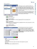
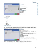
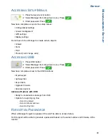
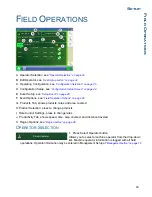
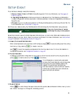
Press the “Select Event” button
and follow the steps in the wizard.
Select Event button opens the Field Operation Wizard where you can enter information relating to your
Growing Season, Grower, Farm, Field, Crop Type and Product. For more information, see
and also
“Field Operation Options” on page 46
.
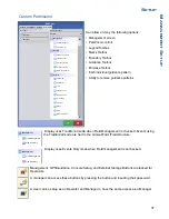
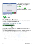
1. Grower, Farm and Field Selection
Enter a Growing Season, Grower, Farm, and Field by pressing
to select existing ones from a drop-
down menu, or by pressing
to create a new one.
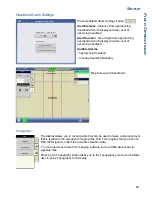
Use
to select an operating configuration from the drop-down menu. For more informations on
Configuration Selection see
“Configuration Selection” on page 25.
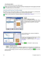
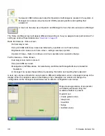
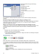
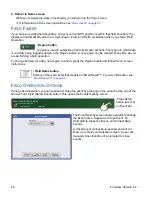
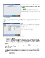
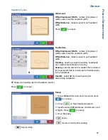
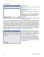
2. Product Selection
A planting or application configuration must include a product. Select product from the drop-down list or
press
to create a new one. Press
to continue.
• If a configuration is loaded with undetected
modules, the Product Selection screen may show
some grayed out (unavailable) options. The
example to the left shows that the Direct
Command module is active but Direct Injection,
Crop Sensor, and Boom Control modules are
grayed out and not functional.
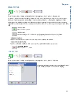
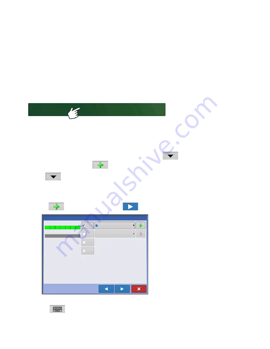
3. Region Options
Press
to edit or change the region name from the system default if desired. At this screen, you can
also create a new region or change the controlling product.
Select Event
Product Selection
DC COM10K
DL1
Crop Sensor
Boom Control
Active
Active
Active
Select Product
Active
28% UAN
Summary of Contents for ag leader
Page 1: ...Operators Manual Firmware Version 5 4 Ag Leader PN 4002722 Rev G ...
Page 2: ...Firmware Version 5 4 ...
Page 20: ...6 Firmware Version 5 4 ...
Page 38: ...24 Firmware Version 5 4 For more information see Legend Settings on page 52 ...
Page 55: ...41 SETUP M ANAGEMENT S ETUP Remove button Press to remove a business ...
Page 56: ...42 Firmware Version 5 4 ...
Page 78: ...64 Firmware Version 5 4 ...
Page 82: ...68 Firmware Version 5 4 Press to Export All Log files Export All Log Files ...
Page 84: ...70 Firmware Version 5 4 ...
Page 94: ...80 Firmware Version 5 4 ...
Page 108: ...94 Firmware Version 5 4 ...
Page 140: ...126 Firmware Version 5 4 ...
Page 154: ...140 Firmware Version 5 4 ...
Page 158: ...144 Firmware Version 5 4 ...
Page 162: ...148 Firmware Version 5 4 ...
Page 222: ...208 Firmware Version 5 4 ...
Page 244: ...230 Firmware Version 5 4 ...
Page 260: ...246 Firmware Version 5 4 ...
Page 290: ...276 Firmware Version 5 4 ...
Page 304: ...290 Firmware Version 5 4 ...


