BEFORE FIRST USE
TOOLS REQUIRED: 4 mm hex drive bit, 10 mm wrench,
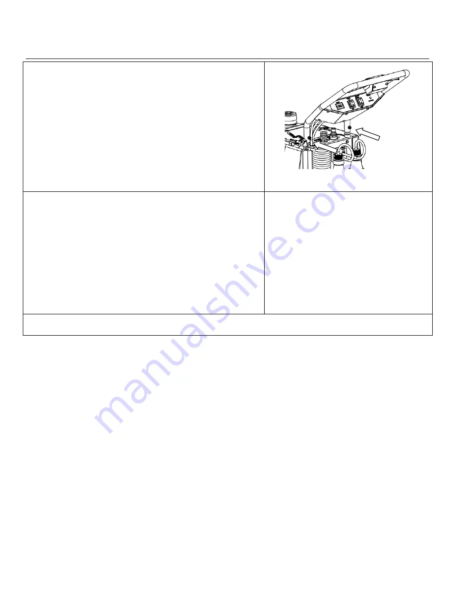
1. Install handle
Using drive and wrench, remove two bolts from
posts. Insert tubes over posts and line up the holes. With tubes in posi-
tion, reinsert two bolts supplied into either the upper or lower holes and
tighten until they are snug. For operator comfort, handle may be fixed
in one of two positions.
After handle is installed, tuck excess cords into top panel.
NOTE: Locate the Accessory/Spare Parts Kit in filter basket. It
contains two sets of impellers and gaskets for servicing pumpout
pump. Set aside for future use.
2. Flush system lines.
Unit may contain residual antifreeze
from the factory. Flush internal lines with fresh water prior to use.
DO NOT drain used antifreeze on the ground or into storm drains. Dis-
pose of antifreeze only in an approved location. Observe local, state,
and federal laws when disposing antifreeze.
A. Flush cleaning head solution lines.
Set
unit up for operation (see “Setup for Cleaning
below), except leave cleaning solution intake
tubes disconnected and direct pumpout dis-
charge hose into a bucket or suitable drain. Op-
erate unit for a few minutes on a hard, water-
proof surface until discharge runs clear.
B. Flush accessory solution line.
Set unit up
for accessory operation (see “Cleaning with Ac-
cessory Tool/Upholstery Tool” below). Place
accessory tool end in a bucket of clean water
and operate the VC700 until discharge runs
clear.
THE VC700 IS NOW READY TO CONNECT TO A WATER SUPPLY AND A DRAIN.
Handle may
be installed
in high or
low position.
VISIT WWW.VERSACLEANSYSTEMS.COM
49-090B VC700-115V 2014-05
4
Legend Brands, Inc.


