


4-7
39014-03 06/16
VERSALIFT VST-36/40/47/52-I
OPERA
TION
to move in the corresponding direction. Lift movement
stops as the control switch is released and returns to
the neutral position.
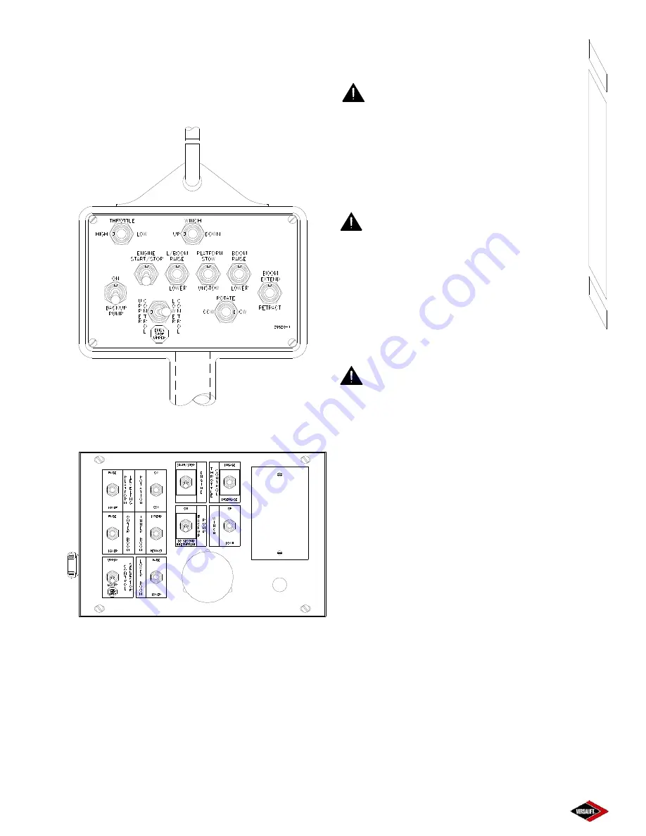
Hand-Held Remote Control
Figure 4.6
Remote Control Box
Figure 4.7
UPPER CONTROL OPERATION
This section describes the controls at the platform.
The Unitrol standard 3-function or optional 4-function
control is presented in this section. Never allow an
untrained individual to operate the aerial lift.
DANGER:
AN UNTRAINED OR
CARELESS OPERATOR SUBJECTS HIM/
HERSELF AND OTHERS TO DEATH OR SERIOUS
INJURY.
When operating the lift, all lift movements must be
started and stopped gradually.
DANGER:
NEVER REVERSE OR STOP
THE DIRECTION OF THE LIFT TRAVEL
SUDDENLY AND AVOID REACHING THE END OF
THE BOOM TRAVEL AT EXCESSIVE SPEEDS.
STRUCTURAL DAMAGE OR INSTABILITY MAY
RESULT CAUSING DEATH OR SERIOUS INJURY.
Never operate the upper controls without using the
personnel restraint system.
DANGER:
NEVER OPERATE ANY
AERIAL EQUIPMENT WITHOUT USING AN
APPROVED PERSONNEL RESTRAINT SYSTEM
ATTACHED TO THE SAFETY RING ON THE
PLATFORM SUPPORT WELDMENT. FAILURE TO
PROPERLY SECURE THE SAFETY BELT AND
LANYARD
MAY RESULT IN DEATH OR SERIOUS
INJURY IN THE EVENT OF A FALL FROM THE
PLATFORM.
Before operating the aerial lift, the operator must be
familiar with the built-in compensation link system
that affects boom movements. The connecting
components are shown on the “Major Components”
drawing in Section 1. When the lower boom function
is activated the lower boom will respond as directed
and the upper boom will move and maintain its initial
position in relation to the turret. However, activating
the upper boom function will not affect the lower boom.
Speed and smoothness of lift operation are controlled
by feathering the control valves. Feathering a control
function allows the operator to change the speed by
adjusting how far the control is moved. Flow can be
directed to one function or multiple functions
simultaneously. Function speed depends on flow to
each valve. Regular practice will develop operator
proficiency.
UNITROL 3 OR 4-FUNCTION CONTROLS
- Refer
to Figure 4.8 for clarification. This multi-jointed handle
operates the valve spools and enables the operator
Summary of Contents for VST-36-I
Page 2: ......
Page 4: ......
Page 6: ......
Page 11: ...2 3 39014 03 06 16 VERSALIFT VST 36 40 47 52 I RESPONSIBILITIES SAFETY ...
Page 12: ...2 4 RESPONSIBILITIES SAFETY 39014 03 06 16 VERSALIFT VST 36 40 47 52 I ...
Page 18: ......
Page 27: ...3 9 39014 03 06 16 VERSALIFT VST 36 40 47 52 I SPECIFICATIONS ...
Page 28: ...3 10 39014 03 06 16 VERSALIFT VST 36 40 47 52 I SPECIFICATIONS ...
Page 29: ...3 11 39014 03 06 16 VERSALIFT VST 36 40 47 52 I SPECIFICATIONS ...
Page 30: ...3 12 39014 03 06 16 VERSALIFT VST 36 40 47 52 I SPECIFICATIONS ...
Page 31: ...3 13 39014 03 06 16 VERSALIFT VST 36 40 47 52 I SPECIFICATIONS ...
Page 36: ...3 18 39014 03 06 16 VERSALIFT VST 36 40 47 52 I SPECIFICATIONS ...
Page 37: ...3 19 39014 03 06 16 VERSALIFT VST 36 40 47 52 I SPECIFICATIONS ...
Page 38: ......
Page 60: ...6 4 39014 03 06 16 VERSALIFT VST 36 40 47 52 I DAILY VISUAL INSPECTION ...
Page 61: ...6 5 39014 03 06 16 VERSALIFT VST 36 40 47 52 I DAILY VISUAL INSPECTION ...
Page 62: ...6 6 39014 03 06 16 VERSALIFT VST 36 40 47 52 I DAILY VISUAL INSPECTION ...


