


4-11
39014-03 06/16
VERSALIFT VST-36/40/47/52-I
OPERA
TION
DANGER:
DO NOT DEPEND ON THE
JIB POLE FOR INSULATION UNLESS THE POLE
HAS BEEN RATED, TESTED, AND MAINTAINED
FOR THE APPROPRIATE LINE VOLTAGE.
THE
WINCH ROPE IS NOT CONSIDERED INSULATING.
IMPROPER USE OF THE JIB POLE OR WINCH
ROPE MAY RESULT IN DEATH OF SERIOUS
INJURY.
Jib Pole Tilt Angle
- The jib pole can be manually
tilted into one of six positions. To adjust the jib pole,
follow the sequence below:
1.
Remove any load from the jib and winch
assembly. Never attempt to adjust the jib while
under load.
2.
Remove the jib tilt lock pin.
3.
Tilt the jib to the desired position.
4.
Fully replace the lock pin.
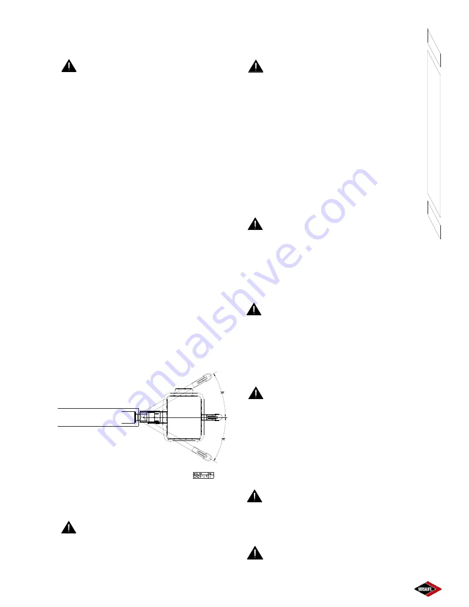
Jib Rotation
- The jib pole assembly can be rotated
to one of three different positions to accommodate a
load. These load lifting positions are located at 0°
and 30° to either side of the boom. See Figure 4.10.
To rotate the jib assembly, follow the sequence below:
1.
Remove any load from the jib and winch
assembly. Never attempt to rotate the jib while
under load.
2.
Remove the jib rotation lock pin.
3.
Rotate the jib to the desired position.
4.
Fully replace the lock pin
Jib-Pole Assembly Rotation Positions
Figure 4.10
DANGER:
ALL JIB POLE POSITIONING
ADJUSTMENTS MUST BE MADE BEFORE
ENGAGING A LOAD. ADJUSTMENT OF THE
ASSEMBLY WITH A LOAD MAY CAUSE DEATH
OR INJURY TO THE OPERATOR AND DAMAGE
TO THE EQUIPMENT.
DANGER:
NEVER OPERATE THE
JIB POLE ASSEMBLY UNTIL THE ASSEMBLY
TURRET IS LOCKED IN A LOAD LIFTING POSITION
AND THE VARIOUS LOCK PINS ARE SECURE. A
LOAD SHIFT CAN CRUSH THE OPERATOR AND
CAUSE DEATH OR SERIOUS INJURY.
HYDRAULIC WINCH OPERATION
- This control is
located in the boom control panel mounted to the
platform. To operate, move the appropriate lever in
the direction indicated on the decal. The winch control
is also duplicated at the lower controls for use in case
of an emergency. When operating from the lower
controls, the winch speed will be slower.
DANGER:
IF THE WINCH ROPE HAS
ABRASIVE WEAR, PULLED STRANDS, CUTS,
HEAT DAMAGE, OR OTHER DEFECTS, IT MUST
BE REPLACED BEFORE FURTHER USE. THE
RECOIL FROM ROPE FAILURE OR FALLING
OBJECTS CAN CAUSE DEATH OR SERIOUS
INJURY TO THE OPERATOR OR GROUND CREW.
DANGER:
PHASE-TO-PHASE OR
PHASE-TO-GROUND CONTACT OF THE WINCH
LINE WILL REDUCE THE STRENGTH OF THE
ROPE.
THE RECOIL FROM ROPE FAILURE OR
FALLING OBJECTS CAN CAUSE DEATH OR
SERIOUS INJURY TO THE OPERATOR OR
GROUND CREW.
DANGER:
NEVER RAISE A LOAD
UNLESS IT IS SECURELY FASTENED. DO NOT
USE THE WINCH LINE TO WRAP OR TIE AN
OBJECT FOR LIFTING BECAUSE THE HOOK ON
THE WINCH LINE MAY DAMAGE OR CUT THE
ROPE. THE RECOIL FROM ROPE FAILURE OR
FALLING OBJECTS CAN CAUSE DEATH OR
SERIOUS INJURY TO THE OPERATOR OR
GROUND CREW.
DANGER:
NEVER USE THE WINCH
TO RAISE PERSONNEL OFF THE GROUND. A
FALL MAY RESULT IN DEATH OR SERIOUS
INJURY.
DANGER:
DO NOT, UNDER ANY
CIRCUMSTANCE, STAND BELOW A SUSPENDED
LOAD. DEATH OR SERIOUS INJURY MAY OCCUR
Summary of Contents for VST-36-I
Page 2: ......
Page 4: ......
Page 6: ......
Page 11: ...2 3 39014 03 06 16 VERSALIFT VST 36 40 47 52 I RESPONSIBILITIES SAFETY ...
Page 12: ...2 4 RESPONSIBILITIES SAFETY 39014 03 06 16 VERSALIFT VST 36 40 47 52 I ...
Page 18: ......
Page 27: ...3 9 39014 03 06 16 VERSALIFT VST 36 40 47 52 I SPECIFICATIONS ...
Page 28: ...3 10 39014 03 06 16 VERSALIFT VST 36 40 47 52 I SPECIFICATIONS ...
Page 29: ...3 11 39014 03 06 16 VERSALIFT VST 36 40 47 52 I SPECIFICATIONS ...
Page 30: ...3 12 39014 03 06 16 VERSALIFT VST 36 40 47 52 I SPECIFICATIONS ...
Page 31: ...3 13 39014 03 06 16 VERSALIFT VST 36 40 47 52 I SPECIFICATIONS ...
Page 36: ...3 18 39014 03 06 16 VERSALIFT VST 36 40 47 52 I SPECIFICATIONS ...
Page 37: ...3 19 39014 03 06 16 VERSALIFT VST 36 40 47 52 I SPECIFICATIONS ...
Page 38: ......
Page 60: ...6 4 39014 03 06 16 VERSALIFT VST 36 40 47 52 I DAILY VISUAL INSPECTION ...
Page 61: ...6 5 39014 03 06 16 VERSALIFT VST 36 40 47 52 I DAILY VISUAL INSPECTION ...
Page 62: ...6 6 39014 03 06 16 VERSALIFT VST 36 40 47 52 I DAILY VISUAL INSPECTION ...


