


4-12
39014-03 06/16
VERSALIFT VST-36/40/47/52-I
OPERA
TION
IF PERSONNEL ARE STRUCK BY FALLING
OBJECTS.
DANGER:
CONTACT BETWEEN AN
ENERGIZED CONDUCTOR AND A WINCH ROPE
EXTENDED TO THE GROUND OR ANOTHER
CONDUCTOR MAY COMPLETE A PATH FOR
ELECTRICITY AND CAUSE DEATH OR SERIOUS
INJURY TO THE OPERATOR OR GROUND CREW.
DANGER:
BEFORE OPERATION
INSPECT FOR LOOSE WINCH MOUNTING
BOLTS. IF LOOSENING OCCURS HAVE THE
UNIT SERVICED AND REPLACE THESE
CRITICAL BOLTS BEFORE FURTHER USE. USE
OF A LOOSE WINCH OR BROKEN
COMPONENTS MAY CAUSE THE EQUIPMENT
TO BREAK LOOSE AND RESULT IN DEATH OR
SERIOUS INJURY TO THE OPERATOR OR
GROUND CREW.
DANGER:
MAKE CERTAIN THE
WINCH-ROPE COILS ARE SPOOLING EVENLY
TO AVOID CLOGGING THE WINCH OR
PRODUCING SHOCK LOADS. AVOID SHOCK
LOADS CAUSED BY JERKING A LINE WITH A
LOAD OR SUDDEN CHANGE IN TENSION FROM
A LIGHT TO A HEAVY LOAD. SHOCK LOADS
MAY CAUSE STRUCTURAL DAMAGE OR
INSTABILITY RESULTING IN DEATH OR
SERIOUS INJURY.
DANGER:
THERE MUST BE AT
LEAST 5 COILS OF ROPE WOUND ON THE
WINCH REEL AT ALL TIMES BECAUSE THE
WINCH DRUM AND ROPE ATTACHMENT ARE
NOT DESIGNED FOR FULL ROPE EXTENSION.
THE RECOIL FROM ROPE DETACHMENT OR
FALLING OBJECTS CAN CAUSE DEATH OR
SERIOUS INJURY TO THE OPERATOR OR
GROUND CREW.
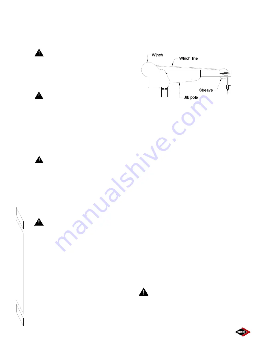
HYDRAULIC JIB OPERATION
The optional material handling system is designed to
lift loads to the work site at the platform. The main
components of this system are the sheave, winch
line, jib pole, and the winch. The jib pole tilts and
extends hydraulically, and rotates manually. Although
some of the components of the jib and winch are made
from non-conductive materials, they are not tested or
maintained as insulating. Therefore, the entire jib and
winch assembly, including the jib pole and rope, must
be considered conductive and have no insulating value.
Hydraulic Jib Major Components
Figure 4.11
Hydraulic Tilt, Extend, And Winch Operation
-
Controls for these functions are located in the upper
control panel mounted to the platform. To operate,
move the appropriate lever in the direction indicated
on the decal. The winch control is also duplicated at
the lower controls for use in case of an emergency.
When operating from the lower controls, the winch
speed will be slower.
Jib Rotation
- The jib pole assembly can be rotated
to one of eight different positions to accommodate a
load. These load lifting positions are located at 0°
and 30° to either side of the boom. See Figure 4.10.
1.
Remove any load from the jib and winch assembly.
Never attempt to rotate the jib while under load.
2.
Remove the jib rotation lock pin.
3.
Rotate the jib to the desired position.
4.
Fully replace the lock pin.
JIB CAPACITY DETERMINATION (VST-36/40/
47-I)
The lifting capacity of the material handling system
is conditional and depends on the angle of the jib
pole, the extension of the inner boom, and the angle
of the outer boom. To determine the lifting capacity
of the jib at a particular position, refer to the
procedure and example below. The capacities
shown here are for example only. Refer to the decals
on the unit for the actual lifting capacities.
DANGER:
NEVER EXCEED THE
MAXIMUM LIFTING CAPACITY AS SHOWN BY
THE MATERIAL HANDLING LOAD CHART.
OVERLOADING THE LIFT MAY CAUSE
EQUIPMENT FAILURE RESULTING IN DEATH OR
SERIOUS INJURY.
Summary of Contents for VST-36-I
Page 2: ......
Page 4: ......
Page 6: ......
Page 11: ...2 3 39014 03 06 16 VERSALIFT VST 36 40 47 52 I RESPONSIBILITIES SAFETY ...
Page 12: ...2 4 RESPONSIBILITIES SAFETY 39014 03 06 16 VERSALIFT VST 36 40 47 52 I ...
Page 18: ......
Page 27: ...3 9 39014 03 06 16 VERSALIFT VST 36 40 47 52 I SPECIFICATIONS ...
Page 28: ...3 10 39014 03 06 16 VERSALIFT VST 36 40 47 52 I SPECIFICATIONS ...
Page 29: ...3 11 39014 03 06 16 VERSALIFT VST 36 40 47 52 I SPECIFICATIONS ...
Page 30: ...3 12 39014 03 06 16 VERSALIFT VST 36 40 47 52 I SPECIFICATIONS ...
Page 31: ...3 13 39014 03 06 16 VERSALIFT VST 36 40 47 52 I SPECIFICATIONS ...
Page 36: ...3 18 39014 03 06 16 VERSALIFT VST 36 40 47 52 I SPECIFICATIONS ...
Page 37: ...3 19 39014 03 06 16 VERSALIFT VST 36 40 47 52 I SPECIFICATIONS ...
Page 38: ......
Page 60: ...6 4 39014 03 06 16 VERSALIFT VST 36 40 47 52 I DAILY VISUAL INSPECTION ...
Page 61: ...6 5 39014 03 06 16 VERSALIFT VST 36 40 47 52 I DAILY VISUAL INSPECTION ...
Page 62: ...6 6 39014 03 06 16 VERSALIFT VST 36 40 47 52 I DAILY VISUAL INSPECTION ...


