Interfaces and Connectors
EBX-41 Reference Manual
28
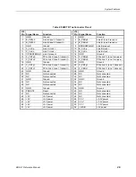
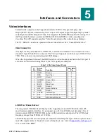
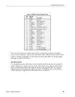
Table 8: LVDS Flat Panel Display Pinout
J32
Pin
Signal
Name
Function
1
GND
Ground
2
NC
Not Connected
3
LVDSA3
Diff. Data 3 (+)
4
LVDSA3#
Diff. Data 3 (
-
)
5
GND
Ground
6
LVDSCLK0
Differential Clock (+)
7
LVDSCLK0# Differential Clock (
-
)
8
GND
Ground
9
LVDSA2
Diff. Data 2 (+)
10
LVDSA2#
Diff. Data 2 (
-
)
11
GND
Ground
12
LVDSA1
Diff. Data 1 (+)
13
LVDSA1#
Diff. Data 1 (
-
)
14
GND
Ground
15
LVDSA0
Diff. Data 0 (+)
16
LVDSA0#
Diff. Data 0 (
-
)
17
GND
Ground
18
GND
Ground
19
+3.3V
+3.3V (Protected)
20
+3.3V
+3.3V (Protected)
The +3.3V power provided to pins 19 and 20 of J32 is protected by a software-controllable
power switch (1 Amp max.). This switch is controlled by the L_VDD_EN signal from the LVDS
interface controller in the Intel® 7 Series Platform Controller Hub (PCH). See the
Intel GM45
Datasheet
for detailed information.
MINI
D
ISPLAY
P
ORT
Two DisplayPorts are provided using two 20-pin mini DisplayPort connectors at locations J26
and J27. DisplayPort consists of three interfaces; main Link, Auxiliary channel, and Hot Plug
Detect. The main Link transfers high speed isochronous video and audio data. The Auxiliary
channel is used for link management and device control. The EDID is read over this interface.
The Hot Plug Detect signal alerts the PCH when a device is connected.


