SPX-5 Reference Manual
5
Physical Details
SPX-5 Board Layout
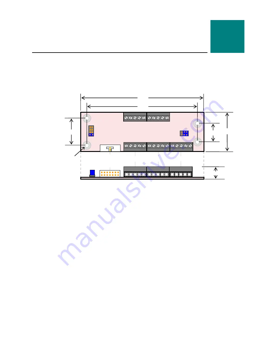
The figure below shows the dimensions of the SPX-5 board, as well as the location of
connectors, jumpers, and mounting holes.
Figure 1. SPX-5 Board Layout
(Not to scale. All dimensions in inches.)
2
1
5
1
1
.2”
3.775”
+
+
+
+
3.375”
J1
SPX to Base
Board
J2
V1
1
0.39”
0.55”
0.8”
0.125” DIA x4
Use 3mm or #4
standoffs
1
5
J3
1
5
J4
5
5
1
1
J6
J5
1
V2


