background image

ii


VL-MPEu-C1E Hardware Reference Manual  


WWW.VERSALOGIC.COM


12100 SW Tualatin Road 

Tualatin, OR 97062-7341 

(503) 747-2261 

Fax (971) 224-4708 


Copyright

©

 2019-2021 VersaLogic Corp. All rights reserved. 


Notice: 

Although every effort has been made to ensure this document is error-free, VersaLogic makes no 

representations or warranties with respect to this product and specifically disclaims any implied warranties of 

merchantability or fitness for any particular purpose. 
VersaLogic reserves the right to revise this product and associated documentation at any time without 

obligation to notify anyone of such changes. 
* Other names and brands may be claimed as the property of others. 


Summary of Contents for VL-MPEu-C1E

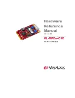
Page 1: ...Hardware Reference Manual REV April 2021 VL MPEu C1E Mini PCIe CAN Module ...

Page 2: ...e to ensure this document is error free VersaLogic makes no representations or warranties with respect to this product and specifically disclaims any implied warranties of merchantability or fitness for any particular purpose VersaLogic reserves the right to revise this product and associated documentation at any time without obligation to notify anyone of such changes Other names and brands may b...

Page 3: ...E product page contains additional information and resources for this product including Reference Manual PDF format Device drivers Data sheets and manufacturers links for chips used in this product Photograph of the circuit board This is a private page for VL MPEu C1E users that can be accessed only by entering this address directly It cannot be reached from the VersaLogic homepage ...

Page 4: ...am 6 RoHS Compliance 7 About RoHS 7 Warnings 7 Electrostatic Discharge 7 Handling Care 7 Technical Support 8 Repair Service 8 Physical Details 9 Board Layout and Mounting 9 VL MPEu C1E Mounting 9 VL MPEu C1E Dimensions and Connectors 9 CAN Termination Jumpers 10 Interfaces and Connectors 11 CAN Connector J1 11 PCIe Minicard Connector 11 LEDS 12 ...

Page 5: ...MPEu C1E supports a wide range of CAN functionality including message acceptance filter and listen only mode The module supports the CANopen higher layer protocol The VL MPEu C1E module is compatible with a variety of popular operating systems including Windows and Linux TECHNICAL SPECIFICATIONS Specifications are subject to change without notification General Specifications Board Size 30 mm x 52 ...

Page 6: ...Introduction 6 VL MPEu C1E Hardware Reference Manual Block Diagram ...

Page 7: ... European Union s RoHS directive Warnings ELECTROSTATIC DISCHARGE Warning Electrostatic discharge ESD can damage circuit boards disk drives and other components The circuit board must only be handled at an ESD workstation If an approved station is not available some measure of protection can be provided by wearing a grounded antistatic wrist strap Keep all plastic away from the board and do not sl...

Page 8: ... of your company your phone number and e mail address The name of a technician or engineer that can be contacted if any questions arise Quantity of items being returned The model and serial number barcode of each item A detailed description of the problem Steps you have taken to resolve or recreate the problem The return shipping address Warranty Repair All parts and labor charges are covered incl...

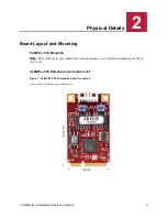
Page 9: ...ut and Mounting VL MPEU C1E MOUNTING Note Be careful not to over tighten the nylon mounting screws Optimum tightness is 1 lbf in 0 1 N m VL MPEU C1E DIMENSIONS AND CONNECTORS Figure 1 VL MPEu C1E Dimensions and Connectors Not to scale All dimensions in millimeters 2 2 ...

Page 10: ...r for CAN Port 1 The jumpers are installed to enable split termination The following are the jumper states for the V1 positions on Port 0 and V2 jumper on Port 1 Table 2 CAN Termination Jumpers CAN Port 0 Jumper Block s Description V1 1 3 and V1 2 4 Split Termination both must be installed V1 1 2 Non Split Termination V1 3 4 Holding Position only no function No Jumpers No termination Table 3 CAN T...

Page 11: ...onnected 6 1 5V 1 5V power NC on MPEu C1E 7 CLKREQ Reference clock request NC on MPEu C1E 8 NC Not connected 9 GND Ground GND 10 NC Not connected 11 REFCLK Reference clock input NC on MPEu C1E 12 NC Not connected 13 REFCLK Reference clock input NC on MPEu C1E 14 NC Not connected 15 GND Ground GND 16 NC Not connected 17 NC Not connected 18 GND Ground GND 19 NC Not connected 20 W_DISABLE Wireless di...

Page 12: ...NC Not connected 45 NC Not connected 46 NC Not connected 47 NC Not connected 48 1 5V 1 5V power 49 NC Not connected 50 GND Ground GND 51 NC Not connected 52 3 3VAUX 3 3V auxiliary source 3 3V power LEDS There are two status LEDs on the minicard A yellow LED D1 for 3 3V minicard power on and a Green LED D2 for the MCU to drive general status Table 4 LED Status and Descriptions LED Reference State D...

Reviews: