10
Eagle Eye Direct
4. C
OMPONENT
I
NSTALLATION
This section covers the installation of the Eagle Eye Direct system components. Before installing the
components, all planning should be completed as described in section 3.
4.1 Cable Installation
When installing reader wiring, use industry standard installation techniques.
Reader wire runs
should allow sufficient length to move ceiling tiles and perhaps to move
readers if needed.
4.2 Reader Installation
Important: When installing the readers, be sure to label both ends of the wire. Keep a list that includes
the labeled number and the location, area, exit or room where the reader is installed.
The single pair reader connections may be up to 1000 feet in length. For connecting readers to the
Eagle Eye Direct controller board, Versus Technology recommends stranded 22 AWG twisted pair
cable.
Handle the readers with care so as not to scratch or damage the casing.
WARNING
!
Always disconnect power from the system before connecting or
d i s c o n n e c t i n g c o m p o n e n t s . F a i l u r e t o d o s o m a y d a m a g e t h e e q u i p m e n t .
Only a single pair of 22 AWG shielded wire is required for each reader. No grounding at the reader is
required. Reader installation calls for use of a splice connector at the reader end of the cable run.
Reader wires are red and black.
To install and wire readers (in ceiling tiles):
1. Create holes for readers in ceiling tiles or ceiling surfaces using a 2-3/8" hole saw.
2. Connect the reader cable wire-pair to each reader (Versus recommends using UY splice
connectors).
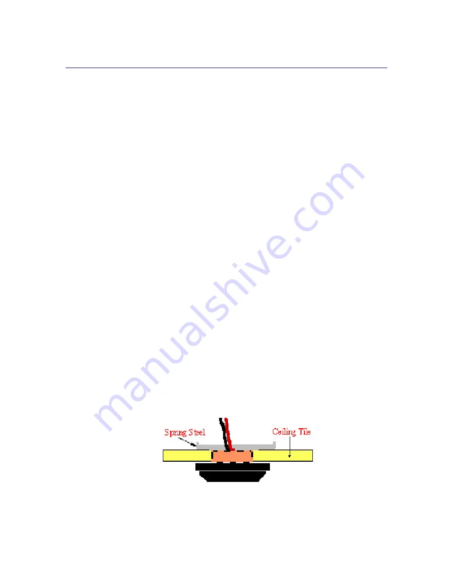
3. Place the reader into the hole and secure using the spring steel clip and the reader cover to
“sandwich” the ceiling tile. The spring steel clip securely holds the reader against the ceiling
tile allowing for easy access for installing or replacing readers.
4. On the Controller Board, connect the red wire (positive) to terminal 13 and the black wire
(negative) to terminal 14 for a “enter” reader. For an “exit” reader, connect the red wire
(positive) to terminal 15 and the black wire (negative) to terminal 16.


