14
Versus Technology, Inc.
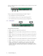
With the controller board facing you and the LED Indicators and the red Switches at the top, the left
most switch is switch 1.
The three red “push buttons” duplicate the functions of terminals 5 through 10.
•
SW1 – Push button one will reset the controller board.
•
SW2 – Push button two will cause all “seen” tags to report to Wiegand Port 1.
•
SW3 – Push button three will cause all “seen” tags to report to Wiegand Port 2.
4.3.3 LED Indicators
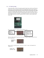
Viewing the LED’s from left to right:
•
LED 1
– indicates power is applied to the controller board.
•
LED 2
– will flash for .25 seconds, anytime a tag transmits its ID and is received by the Versus
room reader.
•
LED 3
– will flash for .25 seconds, anytime a Wiegand ID code is transmitted to Wiegand Port 1.
•
LED 4
– will flash for .25 seconds, anytime a tag transmits its ID and is received by the Versus
exit reader.
•
LED 5
– will flash for .25 seconds, anytime a Wiegand ID code is transmitted to Wiegand port 2.
•
LED 6
– will flash for .5 seconds, anytime a tag transmits a Low Battery or Tamper signal.
•
LED 7
– is a multifunction LED. It will flash once every 2 seconds just to show that the
controller board is operational. It will light continuously, anytime the controller board is
“watching” as many tags at one time as the unit can handle. The controller board can “store” a
maximum of 200 ID codes. If the buffer is full, the “supervision” relay (terminals 3 and 4) will
close for .75 seconds.
LED 1
LED 7
SW1 SW2 SW3


