6
TOGGLE Switch Functions
The
VX-1210
’s
TOGGLE
switch functions can be customized,
via programming by the dealer. Some features may require the
purchase and installation of optional internal accessories. The
possible
TOGGLE
switch programming features are illustrated
at the bottom, and their functions are explained on the next page.
For further details, contact your Vertex Standard dealer.
For future reference, check the box next to each function that has
been assigned to the toggle switch on your particular radio, and
keep it handy.
O
PERATION
Q
UICK
S
TART
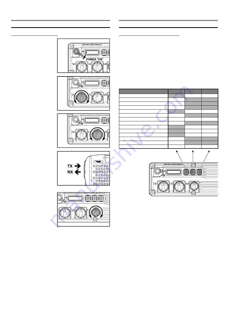
1. Turn the transceiver on
by rotating the
POWER
switch clockwise.
2. Rotate the
SEL
knob to
s e l e c t t h e d e s i r e d
Memory Channel.
3. Rotate the
VOL
knob to
set a comfortable volume
level.
4. To transmit, press and
hold in the microphone’s
PTT
switch, and speak
into the microphone in a
normal voice level. To
return to the receive
mode, release the
PTT
switch.
5. If the frequency of the
station you are receiving
should start to drift, ro-
tate the
CLAR
knob to
follow the drifting signal;
this does
not
cause your
radio’s transmitting fre-
quency to move.
O
PERATION
Operating Manual Reprint
A
DVANCED
O
PERATION
Functions
SELCALL Function
High/Low Power Select
Noise Blanker on/off
Antenna Tuner on/off
Antenna Tuning
Encryption on/off
LAMP on/off
Display Select (Tag/Frequency)
HAIL on/off
VFO/Memory Select
TELCALL Function
Squelch on/off
Speaker Select
None
A
Switch
N/A
N/A
N/A
N/A
N/A
C
Switch
N/A
N/A
N/A
N/A
N/A
N/A
N/A
B
Switch
N/A
N/A
N/A
N/A
N/A
N/A
N/A
Summary of Contents for VX-1210
Page 16: ...16 Note ...
Page 17: ...17 Block Diagram ...
Page 18: ...18 Interconnection Diagram ...
Page 28: ...28 Alignment Note ...
Page 29: ...MAIN Unit 29 Circuit Diagram ...
Page 30: ...30 MAIN Unit Note ...
Page 44: ...44 Main Unit Note ...
Page 45: ...CNTL Unit 45 Circuit Diagram ...
Page 46: ...46 CNTL Unit Note ...
Page 56: ...56 CNTL Unit Note ...
Page 57: ...57 PA Unit Circuit Diagram ...
Page 58: ...58 PA Unit Note ...
Page 65: ...65 Display Unit Circuit Diagram ...
Page 70: ...70 Note ...
Page 71: ...71 Tuner Unit ATU 1210 Option Circuit Diagram ...


