VX-1400 O
PERATING
M
ANUAL
50
I
NSTALLATION
OF
THE
O
PTION
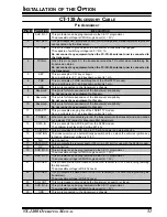
CT-139 A
CCESSORY
C
ABLE
The CT-139 allows connecting the external accessories such as CW Keyer, Data Trans-
mission/Reception Modem, and External Channel Control Input etc.
Ensure that the transceiver is off. Remove the DC Power Cable, Microphone, and
Antenna from the transceiver.
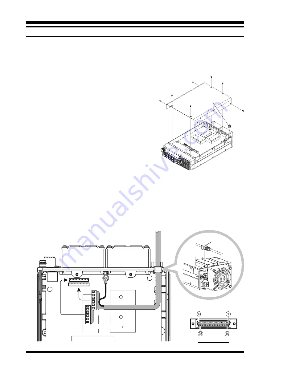
Referring to illustration at the right, remove the
eight screws affixing the Top Cover, and remove
the Top Cover and then remove the Rubber Gas-
ket from the transceiver.
Referring to illustration below, mount the CT-139
Accessory Cable to the transceiver, then connect
the 12-pin connector of the CT-139 to the J4013
on the Main Unit and connect the 13-pin connec-
tor of the CT-139 to the J4012 on the Main Unit
of the transceiver. Connect the Ground Cable of
the CT-139 to the transceiver’s chassis with the
screw fixing the Main Unit while being careful
not to break any electrical parts on the Main Unit.
Fix the wire of the CT-139 so that the wire is not pinched between a part on the Main
unit and the top case.
Replace the Top Cover with its eight screws while being careful so that any wires are
not pinched.
Reconnect the DC Power Cable, Microphone, and Antenna to the transceiver. This
completes installation of the CT-139 Accessory Cable.
Ground Cable
MAIN Unit
J4013
J4012
13-pin Connector
12-pin Connector
Rubber Gasket
Flat
P
IN
A
SSIGNMENT
Summary of Contents for VX-1400
Page 39: ...37 VX 1400 OPERATING MANUAL SELCALL TELCALL OPERATION NOTE ...
Page 55: ......


