1
©2005 VERTEX STANDARD CO., LTD.
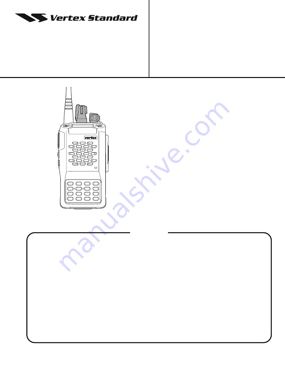
UHF Band
Service Manual
VX-800
Introduction
The Vertex Standard VX-800 is a compact, hand-held
portable transceiver for the UHF land mobile bands
that offers the convenience of small size, light
weight, and simple operation. The VX-800 can be
programmed by your Vertex Standard Dealer with
up to 200 channels for both single and split fre-
quency operation. The VX-800 provides up to 5 watts
of RF output power and includes a flexible quick-
connect antenna.
The transceiver and Ni-Cd, Li-Ion battery packs are
constructed of thick high impact polycarbonate plas-
tic, with special attention paid by the designers to
tight sealing and ruggedness, assuring years of reli-
able operation even in harsh environments.
The following pages describe the operation, features
and accessories of the VX-800. Following the dis-
cussion of transceiver operation, details regarding
programming software, alignment, and mainte-
nance will follow.
VERTEX STANDARD CO., LTD.
4-8-8 Nakameguro, Meguro-Ku, Tokyo 153-8644, Japan
VERTEX STANDARD
US Headquarters
10900 Walker Street, Cypress, CA 90630, U.S.A.
YAESU EUROPE B.V.
P.O. Box 75525, 1118 ZN Schiphol, The Netherlands
YAESU UK LTD.
Unit 12, Sun Valley Business Park, Winnall Close
Winchester, Hampshire, SO23 0LB, U.K.
VERTEX STANDARD HK LTD.
Unit 5, 20/F., Seaview Centre, 139-141 Hoi Bun Road,
Kwun Tong, Kowloon, Hong Kong
Contents
Operating Manual Reprint ................................................................................................................................................ 2
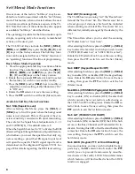
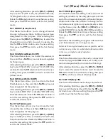
Set (Menu) Mode Functions .............................................................................................................................................. 8
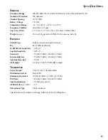
Specification ....................................................................................................................................................................... 11
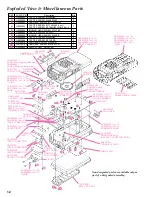
Exploded Views & Miscellaneous Parts ....................................................................................................................... 12
Block Diagram .................................................................................................................................................................... 13
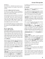
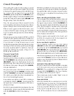
Circuit Description ............................................................................................................................................................ 15
Alignment ........................................................................................................................................................................... 18
Board Units (Schematics, Layouts & Parts)
MAIN Unit ...................................................................................................................................................................... 25
VR Unit ............................................................................................................................................................................ 55
SW Unit ............................................................................................................................................................................ 56
Dummy Unit ................................................................................................................................................................... 57
Optional Board Units (Schematics, Layouts & Parts)
F2D-8 2-Tone Decode Unit ............................................................................................................................................ 58
VTP-50 VX-Trunk Unit .................................................................................................................................................. 60
FVP-25 Encryption / DTMF Pager Unit ...................................................................................................................... 62
F5D-14 5-Tone Unit ........................................................................................................................................................ 64
Summary of Contents for VX-800
Page 10: ...10 Set Menu Mode Functions Note ...
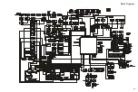
Page 13: ...13 Block Diagram ...
Page 14: ...14 Note Block Diagram ...
Page 24: ...24 Note ...
Page 26: ...26 Main Unit Lot 1 3 Note ...
Page 29: ...29 Main Unit Lot 4 50 Circuit Diagram ...
Page 30: ...30 Main Unit Lot 4 50 Note ...
Page 33: ...33 Main Unit Lot 51 Circuit Diagram ...
Page 34: ...34 Main Unit Lot 51 Note ...


