Page 19
VP-X Installation and Operating Manual
Rev. D (August 5, 2020)
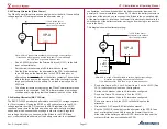
Step 3
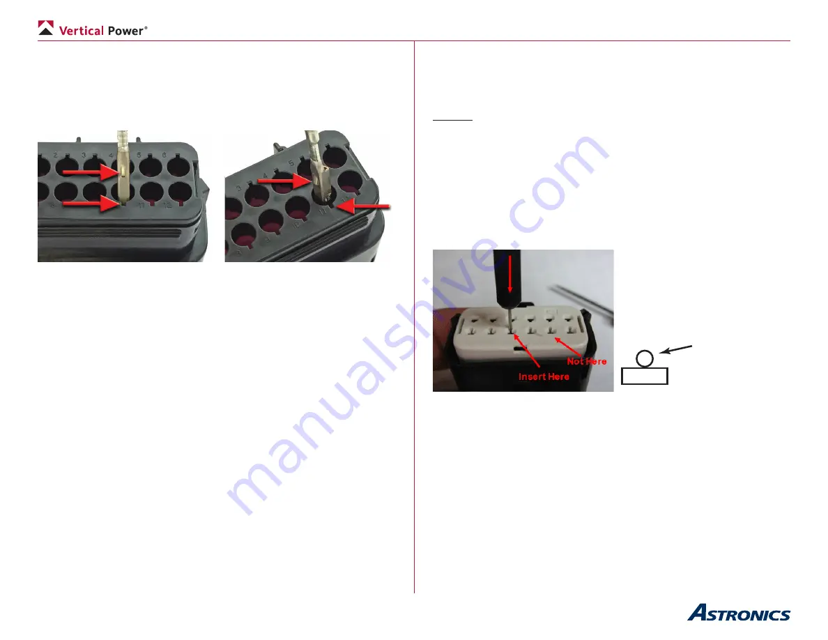
: With the white insert still in the ‘out’ position, align the terminal to
rear of connector. Align the orientation feature as shown and insert through
appropriate opening. If resistance is encountered, retract the terminal and
adjust the angle of insertion. Continue inserting the terminal until it stops with
an audible click. Give the wire a slight tug to make sure it is seated properly.
It should not come back out.
Orientation feature on terminal
90° mis-orientation
aligned with index on housing
Not a straight entry
Troubleshooting:
The terminal should insert smoothly into the connector housing. If it does not,
the following are the most likely causes:
• The terminal is rotating while you are inserting it. The terminal must
remain aligned until it is fully inserted.
• The tangs on the insulation crimp may not be fully closed. Gently
squeeze the tangs closed around the insulation with a pair of pliers.
• The white insert may have closed. Open the insert.
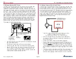
Step 4
: With the terminals fully installed, the white insert can be seated into
its final lock position by applying an even force to both ends until it comes to
a stop, with an audible click. The white insert should move a distance of 5.0
mm (about ¼”).
4.7b Removing terminals
Steps 1 & 2
: Follow these steps as shown above to raise the white part of
the connector.
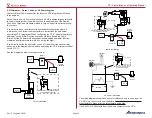
Step 3
: Using the pin removal tool, insert the tip into the terminal service hole
adjacent to the terminal to be serviced.
Step 4
: Push down gently to release locking finger. You will hear a gently
click.
Do not apply any lateral force, as this may damage the connector
or the terminal!
Step 5
: With the white insert still in the ‘out’ position, gently pull on the wire to
release the terminal.
If the terminal resists, the service tool may not be fully engaged. Remove
the tool and re-try. Push the service tool further into the service opening to
ensure that it has fully disengaged the locking finger.
Insert Here
Do not insert the tool into the terminal opening!
Do not use excessive force, excessive force can damage the connector!
Step 6
: The white insert can be seated into its final lock position by applying
an even force to both ends until it comes to a stop, with an audible click. The
white insert should move a distance of 5.0 mm
(about ¼”).


