Page 36
VP-X Installation and Operating Manual
Rev. D (August 5, 2020)
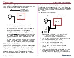
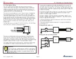
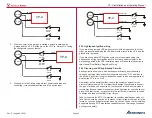
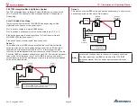
a single power wire. DO NOT wire each power pin on the SkyView to
its own power pin on the VP-X. (see diagram below)
SkyView
Display
Power wire
Solder joint.
D37
1
20
VP-X
•
Configuration instructions are located in the Configuration section
later in this manual.
5.16
Items you don’t have to wire to the EFIS
The following items are traditionally wired directly to the EFIS (optional
of course) but are now integrated into the VP-X and the corresponding
information is sent over a data line from the VP-X to the EFIS. Therefore,
these connections are no longer needed at the EFIS.
• Shunts or hall-effect sensors to measure current
• Trim indicator wires
• Flap indicator wires
5.17 Ground Wiring
All ground wires from the VP-X, trim and flap switches, and panel switches
should terminate at the same ground block. Ground wires from the
avionics should all terminate at a single avionics ground bus. Most lights
can be grounded to the airframe near the light itself. Be sure to follow the
manufacturer’s instructions for grounding for each specific device. Except for
the trim and flap circuits, the VP-X switches only the positive wire and device
grounds should terminate on the airframe or ground block.
The J10 and J12 connector each have a ground wire, and this wire is used to
provide ground to the internal VP-X electronics, trim motors, and flap motor.
The two wires are redundant in case one comes loose.
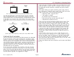
• Connect the two ground wires (J10 Pin 9 and J12 Pin 4) to the
firewall
or main ground block using
18 AWG
wire. Do
not
connect
the two ground wires together and then run a single wire to the
firewall. Both wires should be connected to the same ground block
using an individual connector for each wire.
5.18
General Power Wiring
The VP-X has power pins on J8, J10, J12 and two on J1. These pins are
all wired the same way. Run a wire, sized appropriately for the current load,
from each power pin directly to the load. The connectors on J8, J10, J12
use the larger terminals and the black connectors, and the wire should be
14 to 22 gauge. The J1 connector uses standard male d-sub pins which can
accommodate 20 to 24 gauge wire.
It is not required or recommended to use a capacitor of any size or type on
VP-X outputs.
The following chart should be used to size wires.
Up to (amps)
Use wire size (AWG)
5A
20
10A
18
15A
14
Data signal
22
Trim & flap switch
22
Switches 1 – 10
22
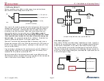
The pin number is shown next to the hole where the wire is inserted on each
connector.
• For each power pin, install a wire from the VP-X connector to the
device. Use the Load Planning Worksheet as a guide.
Stray or Phantom Voltage – It is expected that circuit pins of a powered
VP-X will display a random voltage reading (below bus voltage) on a digital
multimeter when in the “off” condition. See “5.31 Testing Individual Circuits”
on page 53 for more details.


