Page 41
VP-X Installation and Operating Manual
Rev. D (August 5, 2020)
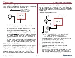
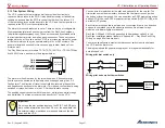
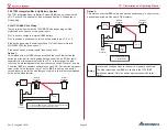
Where to mount the POS-12:
The POS-12 should be mounted so that a pushrod can be attached to both
the POS-12 and to the bell crank on the flap system. The pushrod should
be mounted a certain distance away from its center of rotation so that the
position sensor arm moves 1 inch as the flaps move through their entire
range of travel. This distance can be found through trial and error.
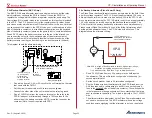
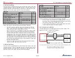
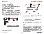
Wiring the flap system
The flap motor is powered through the J12 power connector, and the position
feedback is connected through the J1 d-sub connector. Connect the flaps as
follows:
•
Connect J12 Pins 5 & 6 to the flap motor. Each pin goes to one of
the two wires on the flap motor. The polarity does not matter and can
be changed using the setup menus.
•
If installing a linear flap position sensor, connect J1 Pins 17, 18, 19
to the sensor. The colors on the wiring harness match the colors on a
Ray Allen sensor and can be connected color to color. If you are not
using a Ray Allen sensor, the function of each wire is detailed in the
table above.
•
Connect J2 pins 14 & 15 to flap switch or switches. Connect the
common terminal on the switch to ground.
Important
:
Do not use the flap position inputs on the EFIS. The EFIS gets
flap position information from the VP-X over the serial data line.
Do not install any third-party flap controller module.
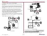
5.20a Flaps System With Limit Switches
Some aircraft like the Lancair Legacy use limit switches to stop the flap motor
at the travel limits. The VP-X does not support the use of these switches
directly. You must therefore wire the flap system outside of the VP-X and use
the VP-X simply to provide power to the flap system. There is a workaround
that may or may not be acceptable to you that is described below.
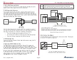
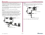
Use a 10A power pin to provide circuit-protected power and wire the flap
switch, flap motor and flap motor limit switches per the wiring diagram
provided by the airframe manufacturer. The flap motor power wires on J12
and flap switch inputs on J2 are not used.
A flap position sensor can be installed and wired as described above (to
show flap position on the EFIS).
There is a way to use the VP-X with flap systems that require limit switches,
but comes with some risk and trade-offs. We will describe those trade-offs
and leave it to you to determine if that is acceptable or not. In this case,
you can use the position sensor instead of the limit switches to stop the flap
motor. The VP-X stops the flap motor at pre-defined stops when configured
as “position” (vs. “momentary”). During configuration, be sure to set the “End
Duration” value to zero or a very low value to minimize run-on. The risks are:
1. There is inherently more slop in the position sensor than the limit
switches, so the flaps may not stop at the exact point you want them
to every time.
2.
If the position sensor fails, the VP-X may not stop the flap motor and
the motor may run past the defined limits and may cause physical
damage to the airframe and/or flap system.
3.
When you run the flaps from the EFIS the position sensor limits are
ignored so it is possible that the flaps can be run past their normal
limits.
5.21
Panel Switches Wiring
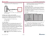
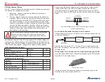
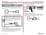
The VP-X turns power pins on and off based on external switches. Each
switch is wired to a discrete input on the VP-X and to ground. When the
switch is closed, it grounds the input pin on the VP-X, signaling the VP-X to
turn on the power pins that are assigned to that switch. You can have any
number of power pins associated with a switch. For example, a switch can
be labeled “Avionics Master” and then all the power pins wired to the avionics
can be assigned to that switch. Another switch can be labeled “Strobe Light”
and the power pin going to the strobe light can be associated with that
switch.
The VP-X performs the actual switching function. There is almost NO current
going through the panel switches. Therefore, you can use any type and style
of switch that you like.


